• Global CNC market projected to reach $128B by 2028 • New EU trade regulations for precision tooling components • Aerospace deman
NYSE: CNC +1.2%LME: STEEL -0.4%

What Safety Checks Are Required for CNC Cutting Operations?

A CNC machine can run a correct part program and still be unsafe. A loose fixture, damaged tool, bypassed door switch, blocked coolant flow, or unverified offset can turn a normal cutting cycle into a broken-tool event, a thrown-workpiece hazard, or an unexpected machine movement.
When asking what safety checks are needed for CNC cutting operations, the practical answer is: inspect the machine’s protective systems, confirm that the workholding and cutting setup can withstand the planned forces, verify the program in a controlled way, and make sure the operator can stop and manage the process safely. These checks should happen before the first cycle, after any meaningful setup change, and whenever the machine behavior no longer matches expectations.
Safety is not separate from production quality. A stable tool, correctly clamped part, and verified program reduce scrap, spindle damage, unplanned downtime, and the risk of injury at the same time.
Start with the machine safety systems
Before focusing on the part or toolpath, check whether the machine itself is safe to operate. CNC lathes, machining centers, and multi-axis machines have different layouts, but the same principle applies: moving components and cutting zones must remain contained while the machine is in automatic operation.
- Guards and enclosure doors: Confirm that guards, windows, doors, and covers are intact, closed, and not damaged. A cracked viewing window or missing cover may not stop machining, but it reduces protection from chips, coolant, or a broken cutter.
- Door interlocks: The machine should not begin an automatic cutting cycle with an enclosure door open. Do not defeat or bypass an interlock to make setup faster. If an interlock does not work reliably, treat it as a maintenance issue rather than an inconvenience.
- Emergency stop: Make sure the emergency-stop button is visible, accessible, and released before startup. Operators should also know what motion and power the emergency stop interrupts on that particular machine, since stopping behavior can differ by machine design.
- Control panel and alarms: Review active alarms before starting. Clearing an alarm without finding its cause can leave a lubrication, axis, spindle, or guarding problem unresolved.
- Chip containment: Check chip conveyors, augers, and collection areas for jams or excessive buildup. Chips should never be cleared by hand while equipment is moving.
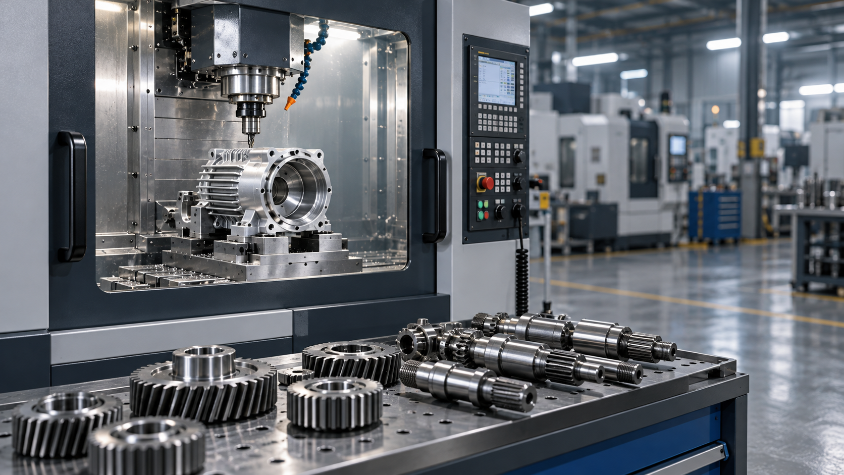
Machine safety checks matter especially on enclosed high-speed machining centers, where chips and coolant can obscure the cutting area. They are equally important on CNC turning machines, where rotating stock, chucks, and bar-feed equipment create hazards that may be less obvious once the cycle begins.
Inspect the cutting tool before it reaches the material
A cutting tool is safe only when it is suitable for the operation, securely retained, and in usable condition. Tool failure often starts with an incorrect setup decision rather than a sudden defect.
Check that the tool type, diameter, insert grade, holder, and stick-out match the programmed operation and material. A long tool extension may be necessary to reach a feature, but it increases deflection and vibration. If the tool chatters, the problem is not always spindle speed or feed rate; excessive projection, weak holder support, or poor tool condition may be the real cause.
Inspect cutting edges for chipping, cracking, wear, built-up material, or loose inserts. On a lathe, confirm that inserts are seated correctly and clamping screws are secure. On a milling machine, verify that the cutter is fully seated in its holder and that the holder is properly clamped in the spindle or tool magazine interface.
Tool data needs the same attention. Incorrect length offsets can drive a tool into the fixture or workpiece before cutting begins. Incorrect diameter or radius values can create an unexpected path near clamps, walls, and finished surfaces. Tool offsets are not merely dimensional settings; they are part of the machine’s collision-prevention system.
Check the spindle and tool-retention condition
Look for signs that the spindle taper, toolholder, collet, or retention components are contaminated or damaged. Chips and coolant residue in a taper can prevent proper seating. A tool may appear installed correctly but run out excessively or release under load if the contact surfaces are compromised.
For machines with automatic tool changers, confirm that the selected tool is in the expected pocket and that no tool is protruding or improperly retained. After manual tool changes, remove wrenches, setup blocks, and measuring tools from the enclosure before closing the door.

Workholding is a safety check, not only a setup step
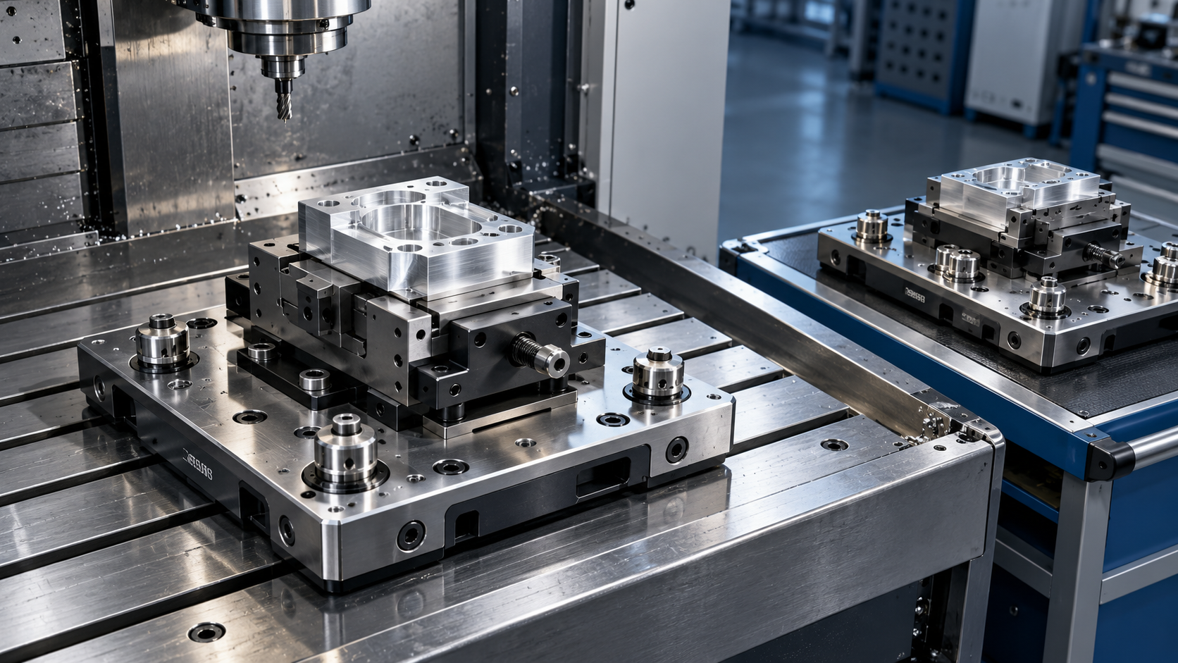
The workpiece must resist cutting forces in every direction the program will apply them. This becomes more demanding when machining heavy components, thin-walled parts, irregular castings, long shafts, or parts that require multiple setups.
For a vise setup, check that the jaws are clean, the part sits fully against the locating surfaces, and the clamping force is appropriate for the material and operation. Chips trapped beneath a workpiece can make a part sit at an angle, affecting both accuracy and grip. For milling, do not assume that a part held securely for light finishing will remain stable during deep roughing or aggressive drilling.
For chuck work on a CNC lathe, verify jaw engagement, clamping condition, and stock projection. A long unsupported bar or shaft may need tailstock support, a steady rest, or a different machining plan. Rotating unsupported stock can whip, bend, or contact the machine enclosure even if the chuck itself is secure.
Also inspect fixtures, bolts, straps, locating pins, and hydraulic or pneumatic clamps. A fixture must be clear of the programmed toolpath at every stage, including rapid moves, tool changes, probing cycles, and part ejection. When a fixture uses hydraulic or pneumatic clamping, confirm that pressure is available and that the clamp has reached its intended position before cycle start.
Verify the program before running at production speed
A proven program still needs verification when the setup changes. Moving a job to another machine, changing a fixture, replacing a toolholder, using a new material batch, or revising work offsets can change the real-world result even when the code is unchanged.
Begin by confirming the correct program revision and part number. Similar filenames, older revisions, and programs written for another machine are common sources of avoidable errors. Check the active work coordinate system, tool offset records, spindle direction, and units. A program that uses the wrong work offset can machine air, cut the fixture, or drive into the table.
Before the first full cut, use the machine’s available verification methods. Depending on the control and machine, this may include graphics simulation, single-block operation, reduced rapid override, feed override, dry-run mode, or a controlled air cut above the workpiece. These methods do not replace careful setup, but they create time to identify an incorrect move before it becomes a collision.
Pay particular attention to the first approach move, the first rapid move after a tool change, and any movement near clamps or machine limits. On multi-axis equipment, safe clearance in one axis position does not guarantee clearance when the rotary axes index or tilt. The operator needs to consider the actual tool, holder, spindle head, fixture, and part orientation throughout the movement.
Do not confuse a simulation with a complete safety check
Offline or control-based simulation is useful for detecting many programming errors. It may not fully represent a worn fixture, an incorrectly loaded tool, a missing clamp, the actual shape of raw stock, or a setup offset entered at the machine. Use simulation to check the intended motion, then validate the physical setup before cutting material.
Confirm coolant, lubrication, and chip control
Coolant is often treated as a machining-quality issue, but it can become a safety issue when it affects tool life, chip evacuation, visibility, or heat. Check coolant level, flow direction, nozzle position, and delivery before a demanding cut. A nozzle that was bumped during setup may no longer reach the cutting edge, particularly on deep pockets, drilling operations, or turning inside bores.
Coolant choice must suit the process and material, but the immediate check is more basic: does the fluid reach the cut, and can chips leave the area? Packed chips can damage the workpiece, overload the tool, interfere with clamps, and create hazards during cleanup. Long-stringy chips in turning operations need a reliable chip-breaking strategy and should not be pulled away by hand.
Check machine lubrication indicators and investigate low-lubrication alarms before operation. Axis and spindle components depend on proper lubrication; continuing to run after a warning can turn a preventable maintenance issue into a mechanical failure.
Use a disciplined first-piece routine
The first part is where setup assumptions meet the actual machine. The safest approach is to make the initial cycle deliberately slower and more observable, especially after a new setup, an unfamiliar program, or a tool replacement.
- Confirm the work area is clear, all setup tools are removed, and doors or guards are properly closed.
- Check the loaded material, fixture position, tool list, work offset, and program revision one more time.
- Run the first approach and early cutting moves using an appropriate reduced-risk verification method.
- Watch chip flow, cutting sound, spindle load behavior, coolant reach, and part stability.
- Stop and inspect after the first critical feature or first part rather than assuming the rest of the cycle will correct itself.
- Measure the part and confirm that the process is producing the intended condition before unattended or repeated operation.
Listening is useful, but it is not enough. Unusual noise, vibration, or changing chip shape can indicate a problem, yet some dangerous setup errors are silent until a rapid move or tool engagement occurs. The physical and program checks need to come first.
Checks that change with the type of CNC operation
Basic CNC cutting safety checks apply to all machines, but each operation has specific concerns. Milling requires close attention to tool clearance around clamps, vise jaws, and deep cavities. Drilling requires secure workholding and chip evacuation, particularly when drilling deep holes. Turning requires attention to chuck condition, bar stock extension, jaw grip, and rotating-part clearance.
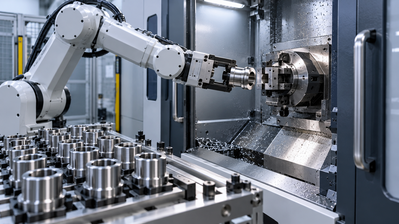
Five-axis machining adds another layer: a collision may involve the toolholder, spindle nose, machine head, rotary table, or fixture rather than the cutting edge alone. Automated cells introduce additional checks for robot motion, pallet transfer, doors, and interlocked zones. The correct response is not simply more inspection. It is to identify which components can move automatically and confirm that each has a protected, predictable path.
For repeat production, a documented setup checklist is useful because it makes critical checks consistent between shifts. The checklist should be practical enough to use at the machine: tool condition, clamp state, offset confirmation, guarding, coolant, first-piece verification, and any job-specific risk points. A generic list cannot replace judgment, but it prevents routine steps from being skipped when production is busy.
Common mistakes that create avoidable risk
One frequent mistake is treating a previous successful run as proof that the next run is safe. A program may be proven, but a new operator, reloaded workpiece, replaced insert, updated offset, or altered fixture changes the conditions.
Another is rushing through setup because the operation looks simple. Short drilling cycles, light finishing passes, and familiar parts can still produce serious incidents when a workpiece is incorrectly seated or the machine is called to the wrong offset. The planned cutting force may be low, but rapid-axis movement and spindle rotation still carry significant risk.
It is also unsafe to reach into a machine to adjust chips, inspect a cut, or retrieve a part while motion continues. Pause the cycle, bring the machine to a safe state, and wait for rotating components to stop. Personal protective equipment supports safe work, but it does not make it acceptable to defeat guards or work near moving machinery.
What should be confirmed before the next cycle?
Before starting CNC cutting, confirm four things: the machine can protect the operator, the tool can perform the programmed cut, the workpiece can remain fixed under load, and the commanded motion matches the actual setup. When any one of those answers is uncertain, the right next step is a controlled inspection or verification run, not a faster cycle start.
That discipline becomes more valuable as CNC production becomes more automated. Precision machine tools and automated production lines can repeat a good process efficiently, but they can also repeat an unchecked error quickly. A reliable safety routine protects people while preserving the accuracy and uptime that CNC equipment is designed to deliver.
Recommended for You
![]() 33rd JIMTOF 2026 Set to Open in Tokyo as Taiwanese Exhibitors Seek OrdersGlobal Machine Tool Trade Research Center
33rd JIMTOF 2026 Set to Open in Tokyo as Taiwanese Exhibitors Seek OrdersGlobal Machine Tool Trade Research Center Which Fixture Type Cuts Changeover Time Most in High-Mix CNC Machining?CNC Machining Technology Center
![]() FANUC Invests $18 Million in Largest U.S. Corporate Automation Training CenterMachine Tool Industry Editorial Team
FANUC Invests $18 Million in Largest U.S. Corporate Automation Training CenterMachine Tool Industry Editorial Team Southeast Asia Machine Tool Market: Comparing Automotive Demand by CountryManufacturing Market Research Center
![]() Zhongshan Xiaolan Machinery Exhibition Opens With Global Product DebutsMachine Tool Industry Editorial Team
Zhongshan Xiaolan Machinery Exhibition Opens With Global Product DebutsMachine Tool Industry Editorial Team Automated Production Machining: Which Parts and Batch Sizes Are a Good Fit?Machine Tool Industry Editorial Team


Aris Katos
Future of Carbide Coatings
15+ years in precision manufacturing systems. Specialized in high-speed milling and aerospace grade alloy processing.
▶
What Is Metal Processing? From Raw Material to Finished Machine PartsCNC Machining Technology Center▶
How long does CNC machine delivery and installation usually take?CNC Machining Technology Center▶
CNC Machine Arrival Inspection: Check Shipping Damage, Accuracy, Safety, and DocumentsCNC Machining Technology Center▶
What Should You Check When a CNC Machine Arrives at Your Factory?CNC Machining Technology Center▶
What Safety Checks Are Required for CNC Cutting Operations?CNC Machining Technology Center
▶
Mastering 5-Axis Workholding Strategies
Join our technical panel on Nov 15th to learn about reducing vibrations in thin-wall components.

Providing you with integrated sanding solutions
Before-sales and after-sales services
Comprehensive technical support