• Global CNC market projected to reach $128B by 2028 • New EU trade regulations for precision tooling components • Aerospace deman
NYSE: CNC +1.2%LME: STEEL -0.4%

How to Choose Metal Machining Processes for Tight Tolerances and Production Volume
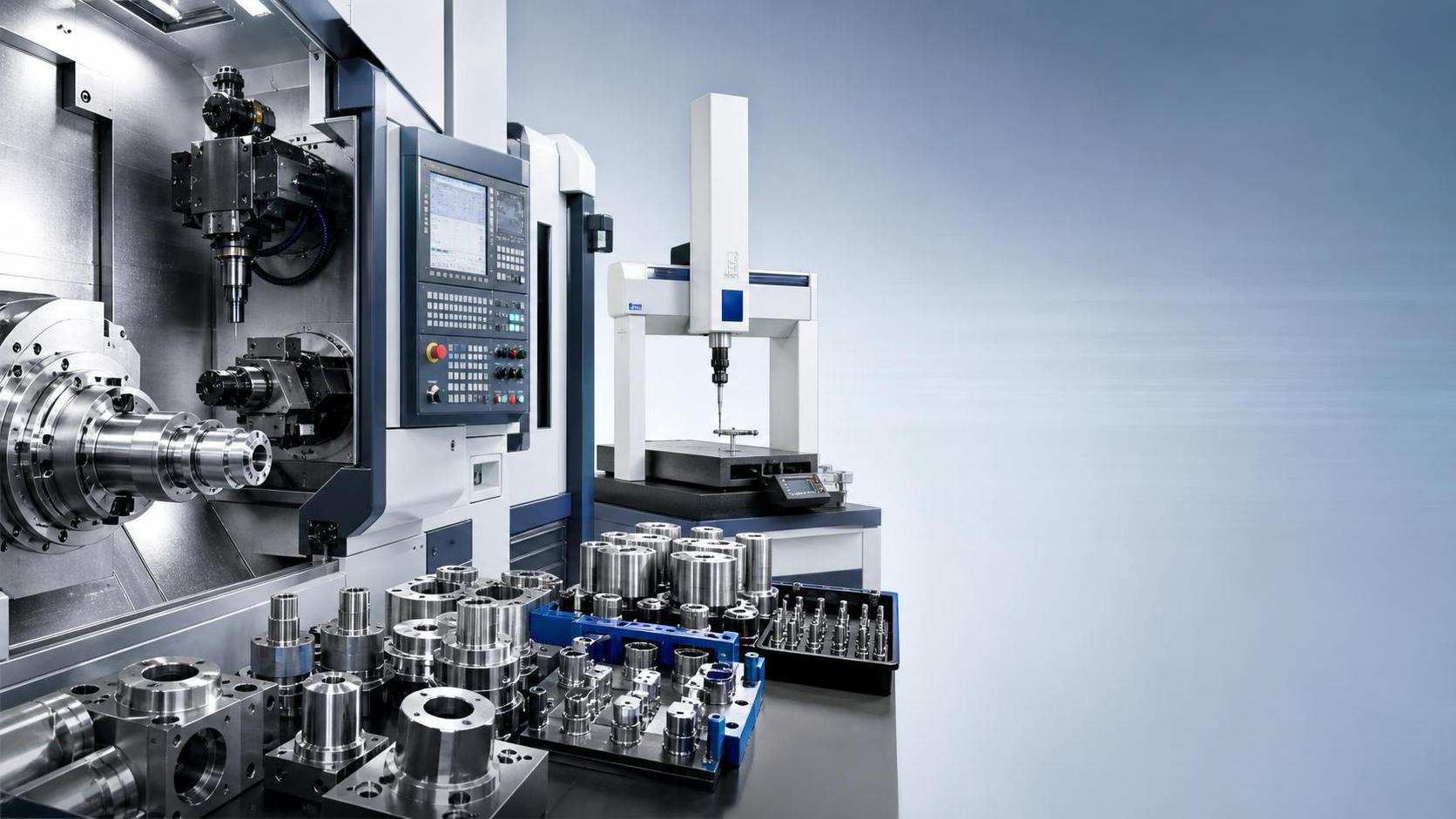
Choosing Metal Machining for Tight Tolerances Is a Process Decision, Not a Machine Decision
A drawing may specify a tight diameter, a controlled flatness requirement, or a precise positional relationship between several features. The immediate question is often, “Which machine can hold this tolerance?” That is necessary, but it is not enough. In practical metal machining, a capable CNC machine can still produce unstable results when the material moves after stress relief, the part is weakly clamped, the datum strategy is unclear, or inspection cannot distinguish process drift from measurement variation.
For technical evaluation, the right process is the one that repeatedly produces conforming parts at the required volume and cost—not merely the one that produces one excellent sample. CNC turning, vertical or horizontal machining centers, five-axis milling, grinding, honing, EDM, and automated machining cells all solve different parts of this problem. A sound selection starts with the functional requirements of the component, then works backward through geometry, material condition, tolerance risk, production volume, fixturing, and verification.
This distinction matters across automotive, aerospace, energy equipment, electronics production, and general industrial manufacturing. A prototype hydraulic sleeve, a medium-volume precision disc, and a high-volume shaft component may share similar dimensions on paper, yet require very different metal machining routes.
Begin With the Functional Tolerance, Not the Smallest Number on the Drawing
Not every tight tolerance has the same manufacturing meaning. A close outside diameter may be relatively straightforward to turn or grind. A close bore diameter combined with strict cylindricity, surface finish, and concentricity to an external datum is more demanding. A positional tolerance on several holes can become difficult when the part distorts after rough machining or when each setup establishes a different reference.
The first review should separate functional features from features that are simply specified more tightly than the application requires. This is not an argument for relaxing a drawing without engineering approval. It is a way to identify where process control deserves the most attention. If a bearing seat, sealing surface, gear interface, or precision locating face drives assembly performance, it should determine the machining route. Decorative faces and non-critical external profiles should not automatically receive the same process burden.
A useful early question is: can the critical features be completed from one stable datum and, ideally, in one final clamping condition? When the answer is no, tolerance stack-up must be evaluated before cycle-time estimates are trusted. Multiple setups are often unavoidable, especially on larger parts, but each transfer adds fixture, datum, and handling variation.
It is also worth checking whether the stated tolerance applies before or after coating, heat treatment, plating, or assembly. In precision manufacturing, many avoidable disputes come from a drawing that does not clearly define the delivery condition of a critical dimension.
Match Geometry to the Natural Strength of Each Process
The most efficient process usually follows the part’s dominant geometry. Rotational components—shafts, sleeves, hubs, flanges, and many disc-shaped parts—typically begin with CNC turning because the workpiece itself rotates around the reference axis. Turning is often the cleanest way to manage concentric outside diameters, shoulders, grooves, threads, and faces. A turning center with live tooling may also complete cross holes, flats, and light milling features without moving the part.
Prismatic housings, plates, brackets, manifolds, and structural components generally favor milling-based routes. Three-axis machining is often sufficient when all critical faces can be accessed through practical reorientation. Four-axis and five-axis machining become valuable when angled holes, compound surfaces, deep pockets, or many orientations would otherwise require repeated setups. The real benefit of multi-axis machining is not simply that it looks more advanced. It is that it can reduce datum transfers, shorten fixture changes, and preserve relationships between features.
That said, five-axis machining is not automatically the best answer for every tight-tolerance part. Complex simultaneous motion can create different challenges in programming, tool deflection, collision control, and verification. For a straightforward precision block, a rigid three-axis or horizontal machining center with a proven pallet and fixture strategy may be more repeatable than an unnecessarily complicated multi-axis route.
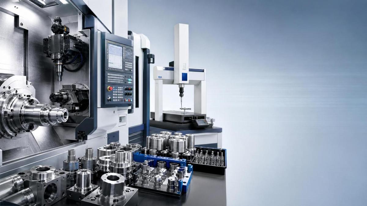
Grinding enters the decision when the required geometry, finish, or material condition is beyond what a cutting operation can consistently deliver. It is particularly relevant after heat treatment, for hardened bearing surfaces, fine cylindrical geometry, and faces requiring close flatness. Honing may be appropriate for bores where surface texture and bore geometry affect sealing, lubrication, or fit. EDM is usually a specialized option for conductive materials with hard-to-machine profiles, internal corners, narrow slots, or features that conventional cutters cannot reach economically.
Material Behavior Can Override an Otherwise Sensible Process Plan
Material selection and material condition should be reviewed before committing to a process. Aluminum alloys, stainless steels, alloy steels, titanium alloys, cast irons, copper alloys, and nickel-based materials do not respond to cutting forces and heat in the same way. Some materials form long chips, some work-harden, some retain residual stress, and some produce rapid tool wear. These behaviors affect more than tool cost; they influence dimensional consistency across a batch.
Thin-walled aluminum parts are a familiar example. They may machine quickly, yet clamping force or asymmetric stock removal can cause movement that is not obvious until the part is released. A large stainless component may remain stable during roughing but shift after substantial material removal. Hardened steel can call for a sequence in which turning or milling establishes stock allowance before grinding finishes the critical surfaces. The exact route depends on alloy, heat-treatment state, geometry, and the permitted tolerance band.
For this reason, “machine complete from raw stock” is not always the lowest-risk plan. A staged route—rough machining, stress-relief or heat treatment where applicable, semi-finishing, and final finishing—can be more predictable. It does add logistics and lead time, so it should be used because the part needs it, not because it sounds more precise.
Production Volume Changes the Economics of Precision
A process that is appropriate for ten components may be uneconomical or unstable at ten thousand. For prototypes and low-volume production, flexible CNC equipment, modular workholding, and operator involvement usually make sense. The goal is to learn quickly: confirm material behavior, prove tool access, identify inspection constraints, and avoid investing in dedicated tooling before the design settles.
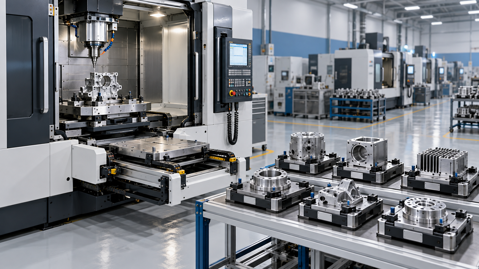
At medium volumes, repeatability begins to matter as much as flexibility. Dedicated soft jaws, hydraulic or pneumatic fixtures, preset tooling, probing routines, and documented setup controls can remove variation that is tolerable in prototype work but costly in recurring orders. This is often the point at which a mill-turn center, palletized machining center, or multi-axis system becomes easier to justify—not because of a headline spindle specification, but because fewer manual interventions are needed.
High-volume production requires a broader view of the cell. Raw material consistency, automated loading, chip evacuation, tool-life monitoring, in-process gauging, part handling, and traceable inspection records may all influence output. Automation should be introduced where it protects the process bottleneck. Automating loading while leaving a highly variable manual measurement step unresolved rarely produces the expected gain.
Volume forecasts should also be treated carefully. If demand is uncertain, a fully dedicated line can become an expensive commitment. Flexible automation, robot-assisted machine tending, or pallet systems may offer a more measured path, particularly in global supply environments where product mixes can change faster than capital plans.
Workholding and Inspection Decide Whether Tight Tolerances Survive Production
In many metal machining projects, the limiting factor is neither the control system nor the cutting tool. It is the fixture. A part that is distorted by clamping may measure correctly while held and move out of specification after release. A fixture that locates on non-functional surfaces can make a part look consistent while losing the datum relationship that the assembly actually needs.
The fixture strategy should mirror the drawing’s datum structure wherever possible. Evaluators should ask how the blank is located, which surfaces are machined in each setup, whether the clamping force is repeatable, and how chips are prevented from affecting seating. For shafts and thin discs, runout control, support strategy, and the sequence of turning operations deserve particular attention. For prismatic parts, the accessibility of probing and the risk of locating on burr-prone edges should be discussed before production release.
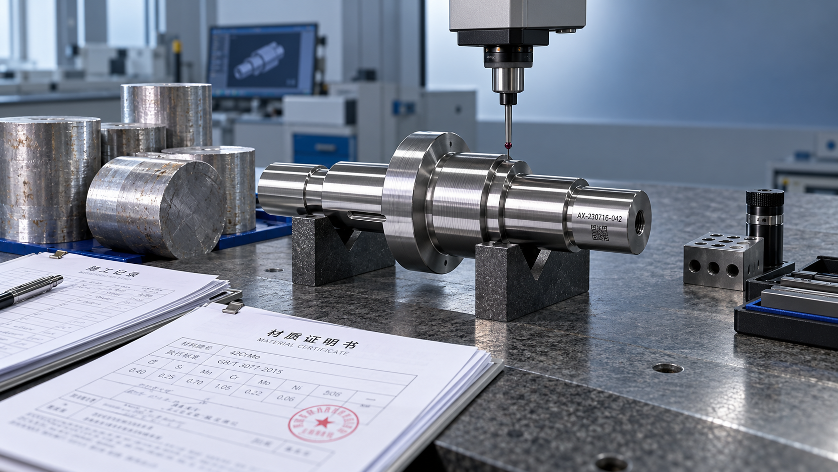
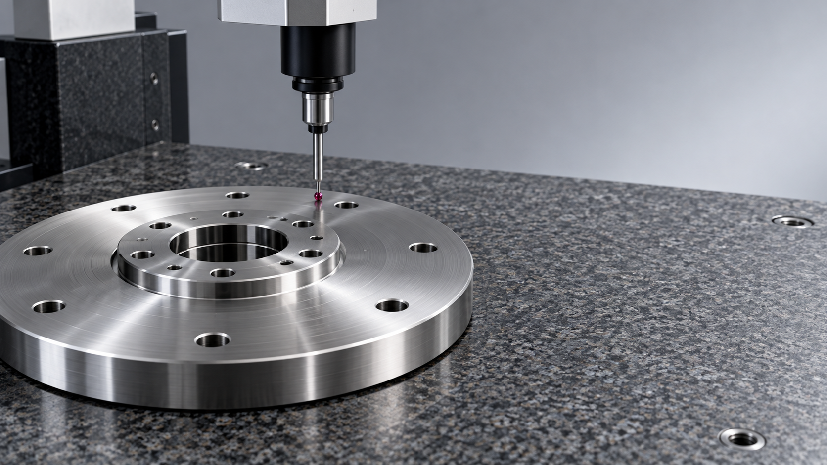
Measurement capability must be aligned with the tolerance being controlled. A coordinate measuring machine may be suitable for complex positional relationships, while bore gauges, air gauges, roundness instruments, surface-finish measurement, and dedicated functional gauges may be more practical for selected production checks. The important point is that the measurement method must be repeatable enough to support process decisions. If inspection variation consumes too much of the allowed tolerance, operators may end up adjusting a stable process in response to measurement noise.
Avoid the Common Shortcut: Selecting by Equipment List Alone
Supplier equipment lists are useful, but they do not prove process capability. Two facilities may both operate five-axis machining centers and grinding equipment, yet differ substantially in fixture engineering, tool management, programming discipline, calibration practice, material control, and inspection planning. For a tight-tolerance component, the better technical discussion is about the proposed routing: how the datums are protected, when critical features are finished, what happens after heat treatment, and how conformity is verified throughout production.
It is sensible to review a representative process plan before awarding work, especially where the part includes thin sections, long unsupported features, deep cavities, hard material, difficult internal geometry, or very close relationships between features made in separate operations. A manufacturability review at this stage can expose design changes that reduce risk without changing function—such as adding realistic tool clearance, avoiding unnecessarily deep internal corners, or clarifying which datum controls a final feature.
A Practical Selection Sequence
The most reliable decision path is straightforward, even if the engineering behind it is not. Identify the features that govern function. Establish the material condition at final inspection. Choose the process that naturally creates the dominant geometry. Then test whether workholding, setup count, finishing operations, and measurement can protect the required relationships at the planned volume.
If the route relies on unusual operator skill, frequent manual adjustment, or measurement that is difficult to repeat, it may still work for a prototype but should not be assumed scalable. Conversely, a process with more deliberate fixturing, automated gauging, or a finishing operation may appear more expensive per part at the outset while carrying less risk in sustained production.
The strongest metal machining choice is rarely the process with the most axes or the shortest theoretical cycle time. It is the route that keeps the critical dimensions tied to stable datums, accounts for material movement, and remains controllable when production moves beyond the first approved part.
Recommended for You
![]() Mitsubishi Electric Announces Physical AI System Linking Humanoid Robots and CNC MachinesMachine Tool Industry Editorial Team
Mitsubishi Electric Announces Physical AI System Linking Humanoid Robots and CNC MachinesMachine Tool Industry Editorial Team Precision Machining for Defense: Supplier Quality and Traceability ChecksManufacturing Market Research Center
![]() Nidec Machine Tool Launches MVR-5X Five-Axis Gantry MachineMachine Tool Industry Editorial Team
Nidec Machine Tool Launches MVR-5X Five-Axis Gantry MachineMachine Tool Industry Editorial Team Choosing a Precision Disc Parts Manufacturer in China: Tolerances and Quality ChecksManufacturing Market Research Center
![]() Siemens Executive Says AI Could Raise Factory Automation to 80%Manufacturing Market Research Center
Siemens Executive Says AI Could Raise Factory Automation to 80%Manufacturing Market Research Center Choosing Automated Machine Tools for High-Mix, Low-Volume ProductionMachine Tool Industry Editorial Team


Aris Katos
Future of Carbide Coatings
15+ years in precision manufacturing systems. Specialized in high-speed milling and aerospace grade alloy processing.
▶
How thermal drift affects accuracy in high-precision manufacturingCNC Machining Technology Center▶
Industrial Machining: Selecting Processes for Tight-Tolerance Metal PartsCNC Machining Technology Center▶
How Does Precision Machining Differ From Standard Machining?CNC Machining Technology Center▶
CNC Precision: Which Tolerances, Materials, and Processes Fit Your Part?CNC Machining Technology Center▶
How to Choose Metal Machining Processes for Tight Tolerances and Production VolumeCNC Machining Technology Center
▶
Mastering 5-Axis Workholding Strategies
Join our technical panel on Nov 15th to learn about reducing vibrations in thin-wall components.

Providing you with integrated sanding solutions
Before-sales and after-sales services
Comprehensive technical support