• Global CNC market projected to reach $128B by 2028 • New EU trade regulations for precision tooling components • Aerospace deman
NYSE: CNC +1.2%LME: STEEL -0.4%

CNC Machining Explained: Processes, Tolerances, and Parts It Can Produce
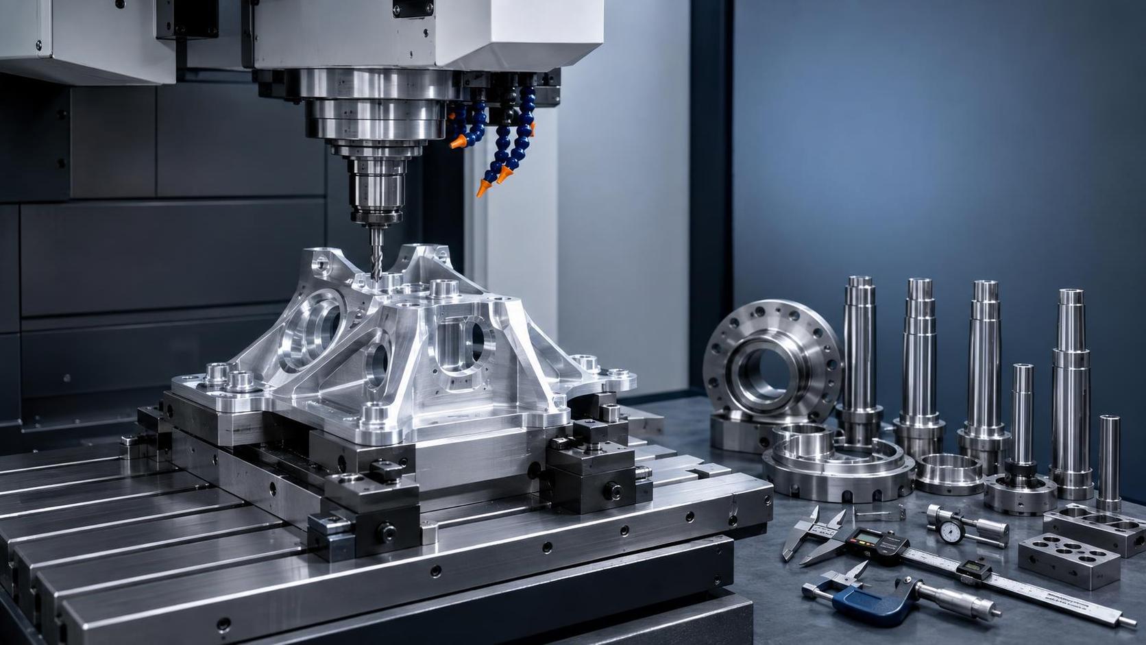
A drawing may look straightforward until it reaches production: a bracket needs holes that line up with another assembly, a shaft must fit a bearing without play, or a small enclosure has features on several faces that are difficult to make by hand. In these situations, the central question is not simply whether a part can be cut from metal or plastic. It is whether the geometry can be produced repeatedly, within the required tolerance, at a practical cost.
CNC machining addresses that problem by using programmed machine tools to remove material according to a digital part model. It can produce accurate prototypes, replacement components, fixtures, and production parts from a wide range of materials. Its practical limits depend on the machine configuration, cutting tool access, material behavior, part rigidity, and the tolerance requirements stated on the drawing. Understanding those limits early helps prevent a common mistake: designing a part that is technically machinable but unnecessarily expensive or difficult to inspect.
How CNC machining turns a digital design into a physical part
CNC stands for Computer Numerical Control. A CNC machine follows coded instructions generated from a CAD model and a machining strategy. Rather than relying on an operator to manually position every cutting tool, the program controls spindle speed, feed rate, tool path, cutting depth, and machine-axis movement.
The workflow usually begins with a 2D drawing or 3D CAD file. The part geometry is then reviewed to identify material, critical dimensions, surface requirements, thread specifications, and features that may require special tooling. CAM software converts the model into tool paths, while the machinist or programmer selects tools, establishes workholding, sets reference points, and determines the sequence of operations.
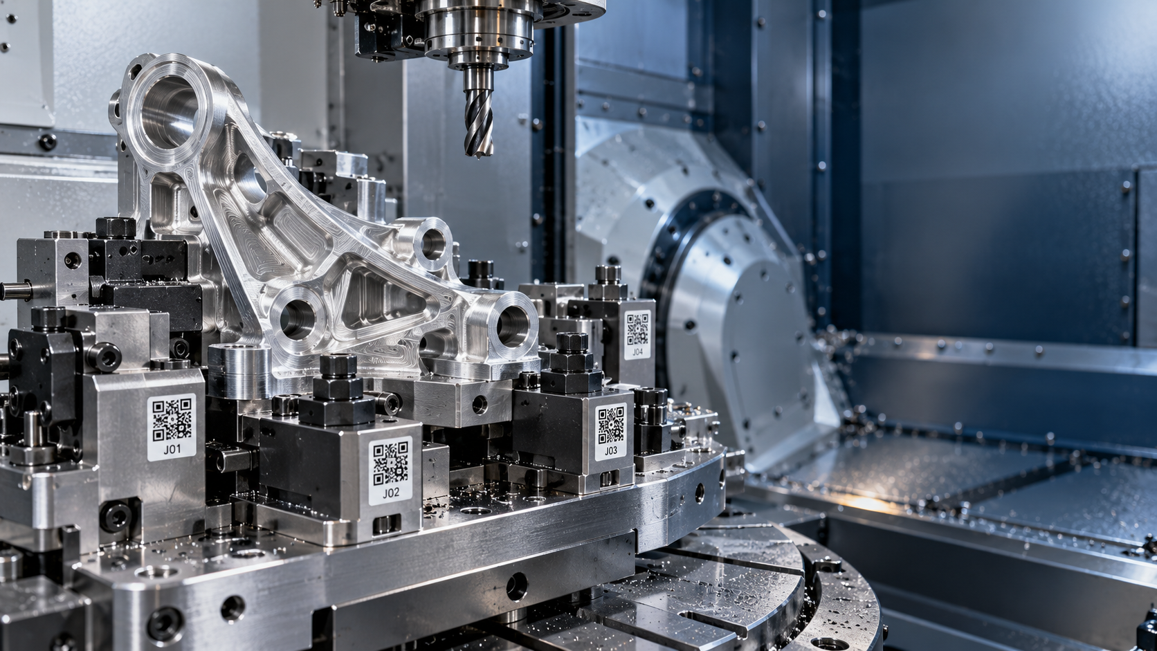
The part is mounted in a vise, chuck, fixture, collet, or custom workholding arrangement. Material is removed in stages rather than in one pass. Roughing operations remove most of the stock quickly. Finishing passes then bring critical surfaces closer to final dimensions and improve surface finish. Features such as holes, pockets, chamfers, threads, and engraved markings may be machined in separate operations.
Programming is important, but it is only one part of the result. A capable program cannot compensate for a thin wall that vibrates during cutting, a poor clamping arrangement, or a tool that cannot physically reach the bottom of a deep narrow cavity. Machining quality comes from the interaction between the design, machine, fixture, tooling, material, and inspection method.
The main machining processes and where each one fits
The term CNC machining covers several processes. The best choice depends on whether the part is primarily rotational, prismatic, flat, or geometrically complex.
CNC milling
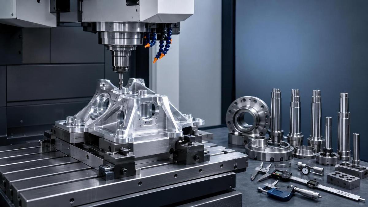
CNC milling uses a rotating cutting tool while the workpiece, the tool, or both move along controlled axes. It is widely used for plates, housings, brackets, manifolds, molds, frames, and structural components. A vertical machining center is especially effective for features on the top face and sides of a part, including pockets, slots, drilled holes, counterbores, and external profiles.
Three-axis milling moves along the X, Y, and Z directions. It is suitable for many parts with accessible features on several planar faces, especially when the part can be repositioned between operations. Four-axis milling adds rotation around one axis, which can simplify machining around cylindrical workpieces or repeated features on multiple sides. Five-axis machines allow the workpiece or cutting tool to tilt and rotate, improving access to angled surfaces, compound curves, and features that would otherwise require several setups.
CNC turning
CNC turning is used when a part is largely symmetrical around a centerline. The workpiece rotates in a chuck or collet while a stationary cutting tool shapes the outside or inside diameter. Shafts, pins, bushings, spacers, threaded fittings, rings, and many valve-related components are typical turned parts.
Turning can create diameters, tapers, grooves, shoulders, bores, and threads efficiently. A lathe with live tooling can also drill cross-holes, mill flats, cut keyways, or add non-round features without moving the part to a separate milling machine. This can reduce handling and improve feature-to-feature alignment, although not every turned design requires that added capability.
Drilling, boring, reaming, and tapping
Holes often receive more attention than their size suggests because they affect assembly directly. Drilling creates an initial hole, but a drilled hole may not provide the final diameter, straightness, or surface quality required for a precision fit. Boring enlarges and corrects a hole, while reaming is used to refine hole size and finish. Tapping produces internal threads, though thread milling may be preferable for certain materials, large diameters, blind holes, or tighter process control.
A drawing that specifies a close-fit dowel pin hole, bearing bore, or sealing surface should make clear which dimensions are functional. Treating every hole as a standard drilled feature can create fit problems later, particularly when mating components are produced separately.
Grinding and secondary operations
Machining centers and lathes can achieve good accuracy, but some surfaces need a secondary process. Grinding is often used where very fine surface finish, high roundness, close dimensional control, or hardened material must be addressed. Deburring, bead blasting, anodizing, plating, heat treatment, laser marking, and assembly may also occur after cutting. These operations should be considered during design because coatings and heat treatment can alter dimensions or affect thread engagement.
What tolerances can CNC machines achieve?
There is no single tolerance that applies to every CNC-machined part. A realistic tolerance depends on the size of the feature, material, geometry, machine condition, tool wear, setup stability, inspection method, and whether the feature is produced in one setup or several. General tolerances may be suitable for noncritical dimensions, while tighter tolerances should be assigned only where function requires them.
For many standard machined features, tolerances in the range of a few hundredths of a millimeter may be practical under controlled conditions. Tighter requirements are possible, but they frequently require slower finishing passes, dedicated fixtures, more careful temperature control, specialized tooling, or grinding. The cost increases not because the number on the drawing is difficult to read, but because every source of variation must be reduced and then verified.
A tolerance callout should communicate a functional need. For example, a close tolerance may be justified on a bearing seat, a sealing land, a locating feature, or a hole pattern that mates with an existing component. It is often unnecessary on an exterior face that has no contact function. Over-tolerancing creates longer cycle times, more inspection, higher rejection risk, and sometimes a need for secondary processing.
Geometric tolerances are especially useful when size alone does not define function. Position controls can clarify how holes relate to datums. Perpendicularity can govern whether a mounting face sits squarely against another component. Runout may matter for rotating parts, while profile tolerances can control complex surfaces. The datum scheme should reflect how the part will be located and used in the finished assembly, not merely the easiest dimensions to place on a drawing.
Parts CNC machines can produce
The range of CNC-machined parts is broad because the process starts with solid stock rather than a dedicated mold. This makes it useful when geometry changes are likely, volumes are modest, or the material must have specific mechanical properties.
Common examples include:
- Rotational components: shafts, axles, threaded adapters, bushings, couplings, collars, pins, pulleys, and retaining rings.
- Prismatic parts: mounting brackets, base plates, machine guards, frames, heat sinks, sensor mounts, and electrical enclosures.
- Fluid-handling components: manifolds, valve bodies, pump housings, fittings, and machined interfaces requiring controlled sealing surfaces.
- Precision assembly elements: jigs, fixtures, nests, gauges, alignment blocks, soft jaws, and robotic end-of-arm tooling.
- Complex structural pieces: lightweight aerospace-style brackets, impellers, contoured supports, multi-face housings, and components with angled or curved features.
- Small technical parts: connector shells, optical mounts, laboratory hardware, instrument components, and custom electronic hardware.
Material selection shapes what the machine can produce efficiently. Aluminum is commonly chosen for its machinability, low weight, and corrosion resistance after suitable finishing. Steel provides strength and wear resistance but may require more cutting force. Stainless steel is useful where corrosion resistance matters, although it can work-harden and generate heat during machining. Brass machines well and is often selected for fittings or electrical parts. Titanium offers a high strength-to-weight ratio but requires careful tool and heat management. Engineering plastics such as acetal, nylon, PEEK, and polycarbonate can also be machined, but their tendency to flex, absorb moisture, or move with temperature should be considered.
Design details that often determine cost and manufacturability
A part can appear simple on screen while containing features that slow production significantly. The most frequent issue is internal corner geometry. Milling cutters are round, so an internal pocket corner naturally has a radius. A sharp inside corner requires a smaller tool, an additional operation, or a different manufacturing process. Unless a sharp corner serves a specific assembly purpose, adding a practical radius usually improves machinability.
Deep narrow pockets present another challenge. The deeper a cutter reaches relative to its diameter, the more likely it is to deflect or vibrate. This can affect wall finish, dimensional accuracy, and cycle time. A design may be improved by widening the pocket, reducing depth, opening one side, or splitting a component into parts that can be assembled.
Thin walls and long unsupported features can move during machining as material is removed. This does not mean they are impossible to produce, but the fixture strategy becomes more important. The part may need to be machined in stages, supported by temporary material, or finished with lighter cuts. Tight tolerances on flexible features deserve particular scrutiny because the measurement may change after the part is released from clamping.
Threaded features should also be designed with the manufacturing route in mind. Blind tapped holes need enough depth for the usable thread length plus the incomplete threads at the bottom. Thread callouts should state the standard, size, pitch, and depth. On small parts, placing threads too close to an edge can leave insufficient material and increase the risk of deformation or breakout.
Choosing between 3-axis, 4-axis, 5-axis, and turning
The most advanced machine is not automatically the best choice. The right process is the one that achieves the required geometry and accuracy with stable setups. A straightforward rectangular bracket with holes and pockets may be well suited to 3-axis milling. Repositioning it once or twice can be more economical than using a complex multi-axis strategy.
Five-axis machining becomes valuable when a part has compound angles, sculpted surfaces, features around several sides, or difficult tool-access requirements. It can reduce the number of setups, which may improve relationship accuracy between features. However, additional capability does not erase design limitations. A narrow internal channel remains difficult if the tool cannot enter it, and extremely tight dimensions still require a sound datum plan and inspection approach.
Turning is usually the starting point for cylindrical parts. When a shaft also needs flats, holes, or milled profiles, a turn-mill machine or a secondary milling operation may be appropriate. The decision depends on volume, tolerance relationships, handling time, and whether moving the part between machines introduces alignment risk.
Questions to resolve before requesting a machining quote
A complete drawing reduces uncertainty more effectively than a long description. The most useful package usually includes a 3D model, a dimensioned drawing, material specification, finish requirement, thread details, critical tolerances, and any inspection expectations. Mating-part information can also be valuable when a feature must fit an existing assembly.
Before finalizing the design, identify which dimensions are truly critical. Ask whether a cosmetic surface needs the same finish as a sealing surface, whether a hole needs a clearance fit or a precision location, and whether several features must be machined in the same setup. Clarifying these points early allows the process to be selected around the part’s real function rather than around assumptions.
Practical questions about CNC-machined parts
Can CNC machining make both prototypes and production parts?
Yes. It is often used for prototypes because design changes can be made by revising the program rather than creating new tooling. It can also support production when the quantity, material, accuracy, and part geometry make machining appropriate. For very high-volume parts with simple geometry, molding, stamping, casting, or forming may become more economical, but those processes involve different tooling and design constraints.
Is a tighter tolerance always better?
No. A tighter tolerance is better only when it improves fit, motion, sealing, alignment, or another functional requirement. Applying close limits everywhere can make a part harder to machine and inspect without improving its performance.
Can a machined part have sharp internal corners?
Not with a standard rotating milling cutter alone. Internal corners will have a radius related to the cutter diameter. Special operations can reduce the remaining radius in certain cases, but they add time and may not be necessary unless another component requires a sharp corner.
PREVIOUS ARTICLE
NEXT ARTICLE
Recommended for You
![]() FANUC Links FIELD System Data with Copilot to Advance Shop-Floor Data UseCNC Machining Technology Center
FANUC Links FIELD System Data with Copilot to Advance Shop-Floor Data UseCNC Machining Technology Center Smart Manufacturing for Aerospace: Building Traceability Across CNC OperationsCNC Machining Technology Center
![]() Mitsubishi Electric Announces Physical AI System Linking Humanoid Robots and CNC MachinesMachine Tool Industry Editorial Team
Mitsubishi Electric Announces Physical AI System Linking Humanoid Robots and CNC MachinesMachine Tool Industry Editorial Team Precision Machining for Defense: Supplier Quality and Traceability ChecksManufacturing Market Research Center
![]() Nidec Machine Tool Launches MVR-5X Five-Axis Gantry MachineMachine Tool Industry Editorial Team
Nidec Machine Tool Launches MVR-5X Five-Axis Gantry MachineMachine Tool Industry Editorial Team Choosing a Precision Disc Parts Manufacturer in China: Tolerances and Quality ChecksManufacturing Market Research Center


Aris Katos
Future of Carbide Coatings
15+ years in precision manufacturing systems. Specialized in high-speed milling and aerospace grade alloy processing.
▶
FANUC Links FIELD System Data with Copilot to Advance Shop-Floor Data UseCNC Machining Technology Center▶
Smart Manufacturing for Aerospace: Building Traceability Across CNC OperationsCNC Machining Technology Center▶
Choosing a CNC Machine for Mold Making: Accuracy, Rigidity, and Surface FinishCNC Machining Technology Center▶
How to Cut CNC Machining Energy Use per Part Without Longer Cycle TimesCNC Machining Technology Center▶
Will a Mazak CNC retrofit work with your existing servo drives?CNC Machining Technology Center
▶
Mastering 5-Axis Workholding Strategies
Join our technical panel on Nov 15th to learn about reducing vibrations in thin-wall components.

Providing you with integrated sanding solutions
Before-sales and after-sales services
Comprehensive technical support