• Global CNC market projected to reach $128B by 2028 • New EU trade regulations for precision tooling components • Aerospace deman
NYSE: CNC +1.2%LME: STEEL -0.4%

Heavy-Duty Machine Tool Applications for Large Industrial Components
Heavy-Duty Machine Tool Applications for Large Industrial Components
Large industrial parts rarely fail a machining plan because someone selected the wrong spindle speed alone. The bigger problems are usually more fundamental: an oversized workpiece shifts during clamping, a long bore loses alignment after roughing, a fixture blocks tool access, or a machine that looks capable on paper cannot hold accuracy once heavy interrupted cuts begin.
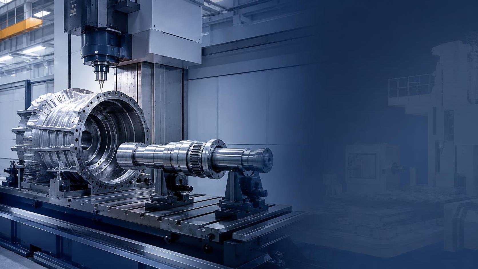
That is where a heavy duty machine tool becomes a project decision rather than simply a capital-equipment purchase. For components such as turbine casings, wind-energy hubs, marine shafts, large gearbox housings, pressure equipment, mining frames, and structural assemblies, machining capacity must be judged as a complete system. Machine rigidity matters, but so do workholding, part handling, process sequencing, inspection access, programming strategy, and the supplier’s ability to support an unusually demanding job.
For engineering leaders, the practical question is not “Which machine is biggest?” It is “Which machining arrangement can produce this part repeatedly, safely, and within the project schedule without creating a chain of avoidable risks?”
Why Large Components Change the Machining Equation
A component can be large without being difficult, and difficult without being particularly large. The trouble begins when size, weight, material condition, geometric complexity, and tolerance requirements appear together. A forged shaft may be straightforward to turn, for example, until it includes deep internal features, bearing seats with tight runout requirements, or surfaces that must remain aligned after several repositioning operations.
Heavy-duty applications are often dominated by stiffness. The machine structure, guideways, spindle, rotary table, and clamping system must resist forces that would be modest in a smaller machining center but become significant with large cutters, broad cutting engagement, or difficult materials. If the setup is not stable, chatter can damage both the surface and the cutting tools. More importantly, vibration can create dimensional variation that is only discovered after a costly part has already moved to inspection or assembly.
Thermal behavior also becomes more visible at this scale. Long machining cycles, large castings, changing shop temperatures, and heavy roughing passes all introduce heat. A project team should not assume that nominal positioning accuracy tells the whole story. The relevant issue is whether the machine and process can maintain the required geometry from the first critical cut through final finishing.
This is one reason CNC lathes, horizontal boring mills, portal machining centers, vertical turning lathes, and multi-axis systems often overlap in large-part projects. Their roles differ, but the final decision usually depends on the component’s dominant geometry and the number of setups needed to complete it.
Matching the Machine Configuration to the Component
A heavy duty machine tool should be selected around the part family, not around a catalog category. A vertical turning solution may be the practical choice for a large ring, flange, wheel, or cylindrical casing because gravity supports the workpiece on the table. It can simplify loading and provide stable access to diameters and faces. But if the part requires extensive off-axis drilling, angled milling, or deep side features, the process may require a second machine unless the platform includes suitable milling capability.
For long shafts, rotors, and cylindrical energy components, a heavy-duty CNC lathe or turning center is often central to the process. The important detail is not merely swing diameter or distance between centers. Teams should examine how the component will be supported throughout roughing and finishing. Tailstock capability, steady rests, spindle torque at usable cutting speeds, chip evacuation, and access for in-process measurement can matter more than an impressive maximum work envelope.
Large structural frames, gearbox bodies, and fabricated equipment bases usually point toward horizontal boring and milling machines or gantry-type machining centers. These parts create a different set of concerns. The machine must reach multiple faces without excessive re-clamping, while the fixture must support a workpiece that may not have consistent casting or fabrication surfaces. If the design includes many datum relationships across a long structure, minimizing setups becomes a direct quality-control measure.
Five-axis or multi-axis machining is valuable when complex access genuinely reduces setups, not simply because it is technologically attractive. In aerospace structures, impellers, complex valve bodies, and some energy equipment, continuous or indexed multi-axis motion can eliminate awkward secondary operations. Yet it also increases programming, collision-control, and post-processing demands. For a one-off or low-volume project, the additional capability only pays off if it removes a real bottleneck in accuracy, handling, or lead time.
The workpiece is part of the machine system
Project planning sometimes treats the machine tool and the fixture as separate purchases. In reality, they behave as one system. A rigid machine cannot compensate for a poorly supported fabricated frame, an undersized chuck arrangement, or a fixture that distorts a thin-walled casting when clamps are tightened.
Before approving a machining route, it is worth reviewing the workpiece in its actual condition: forged, cast, welded, stress-relieved, pre-machined, or partially assembled. Welded structures may move after material removal. Castings may arrive with variable stock allowance. Forgings may need substantial roughing before reliable datum surfaces exist. These are normal manufacturing realities, but they need to be visible in the process plan rather than discovered during setup.
Applications Where Heavy-Duty Capacity Earns Its Place
Energy equipment is a clear example. Turbine casings, generator frames, large valve bodies, hydro components, and wind-power drivetrain parts often combine bulky dimensions with difficult-to-reach features. Their machining route may include large-bore operations, machined sealing surfaces, threaded connections, precise mating faces, and critical alignment features. The challenge is rarely one operation. It is preserving the relationship between those operations after the component has been moved, rotated, and inspected.
In marine and offshore work, propeller shafts, stern-tube components, gearbox housings, winch parts, and large flanges bring additional handling concerns. Saltwater service conditions may place demands on material selection and surface integrity, while the workshop must handle heavy parts without introducing damage during lifting. A machining plan that ignores crane paths, loading orientation, or safe turning of the workpiece is incomplete.
Mining and construction equipment place a different emphasis on durability and repairability. Large excavator structures, crusher bodies, hydraulic-cylinder components, and transmission parts may require machining after welding, rebuilding, or hardfacing. In these jobs, the exact condition of the incoming part can vary considerably. Flexible fixturing and probing strategies are often more useful than a highly optimized program designed only for ideal, repeatable blanks.
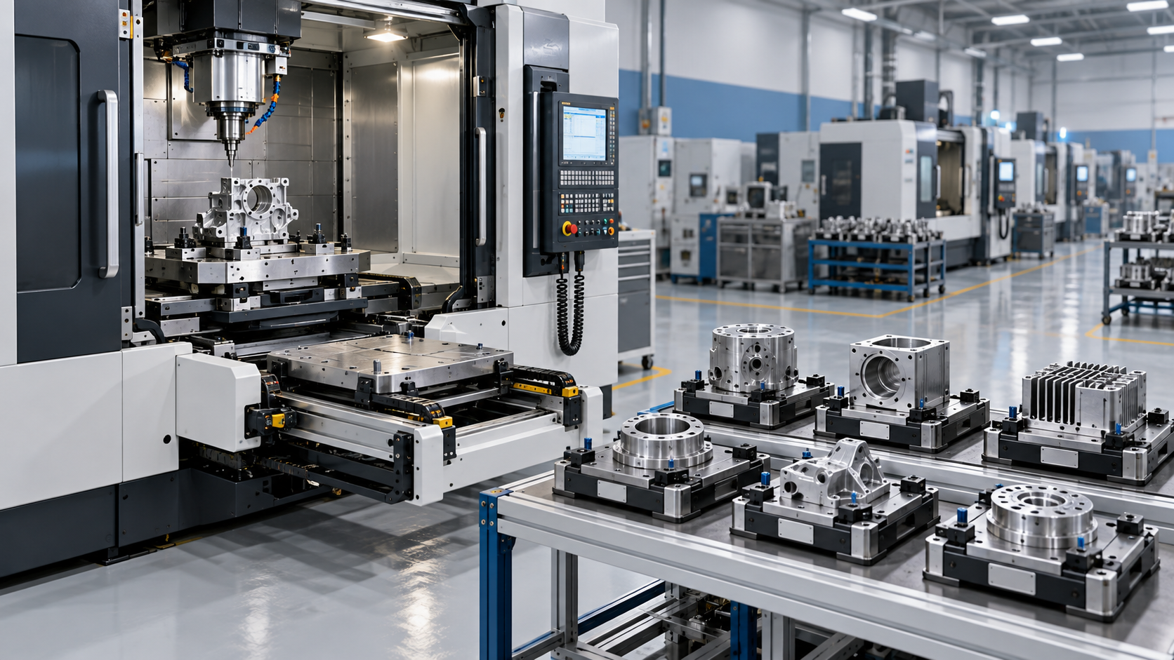
Automotive and electronics manufacturing are usually associated with smaller, higher-volume parts, but they also depend on heavy-duty equipment upstream. Dies, molds, large battery-production fixtures, automation bases, and transfer-line structures all need accurate machining. Here, the decision may be less about cutting the heaviest workpiece and more about integrating repeatable CNC machining with automated loading, pallet systems, robotic handling, and traceable inspection routines.
What to Review Before Committing to a Machine or Process Route
Machine specifications are necessary, but they are only the starting point. A useful technical review should place the actual component beside the actual manufacturing sequence. It should answer questions that are easy to miss during an early budget discussion:
- Can the machine handle the finished part weight as well as the incoming blank weight, fixture weight, and any counterbalance requirements?
- Is there enough travel and tool clearance for the longest tool, largest boring bar, and inspection probe—not only for the part envelope?
- How many times must the component be re-clamped, and which critical dimensions cross those setups?
- Will the spindle and tooling package provide useful torque in the real machining range for the selected material?
- What happens to chips during deep boring, large-diameter turning, or milling inside a cavity?
- Can the shop inspect critical surfaces without removing the part too early from its controlled setup?
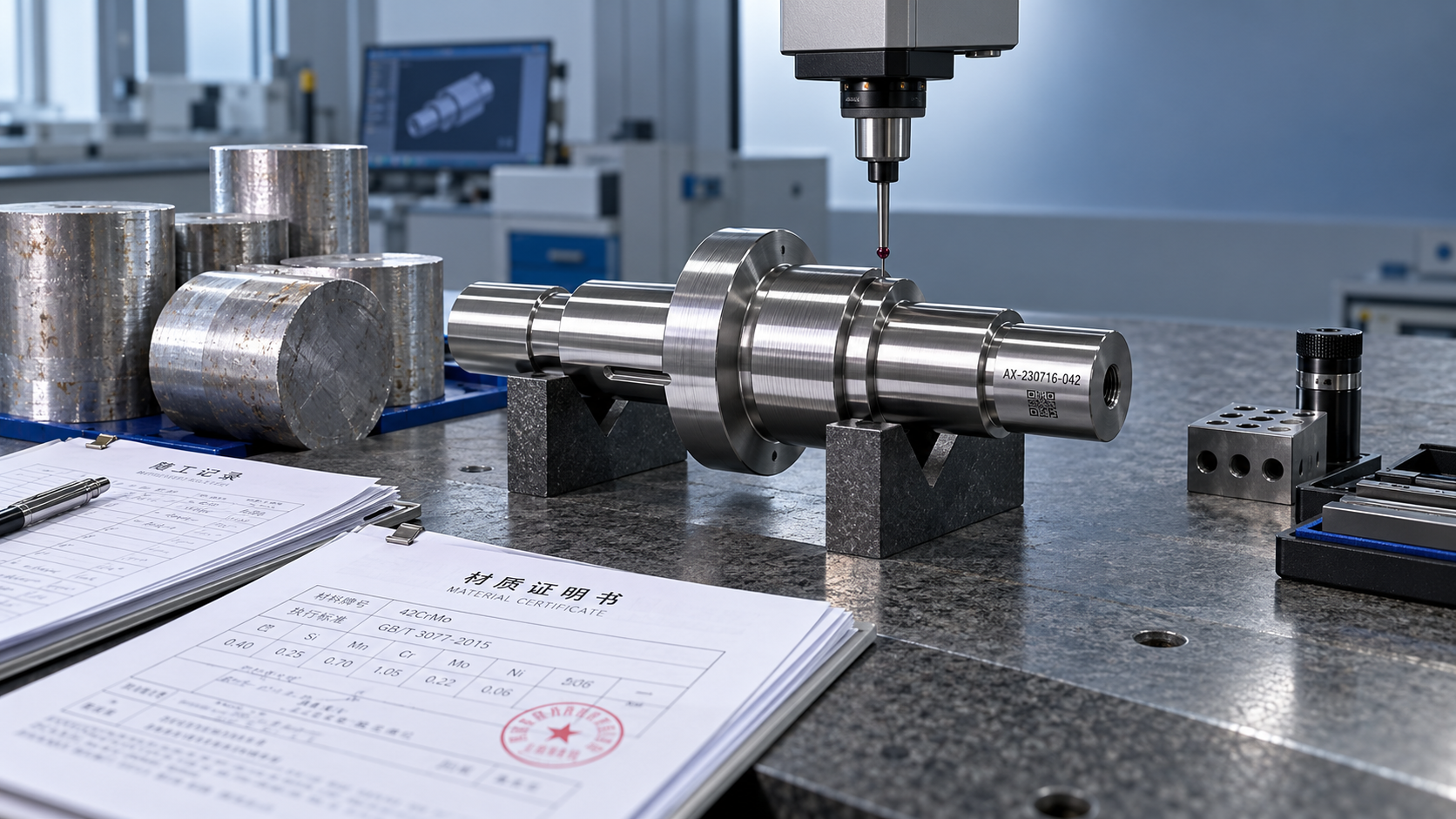
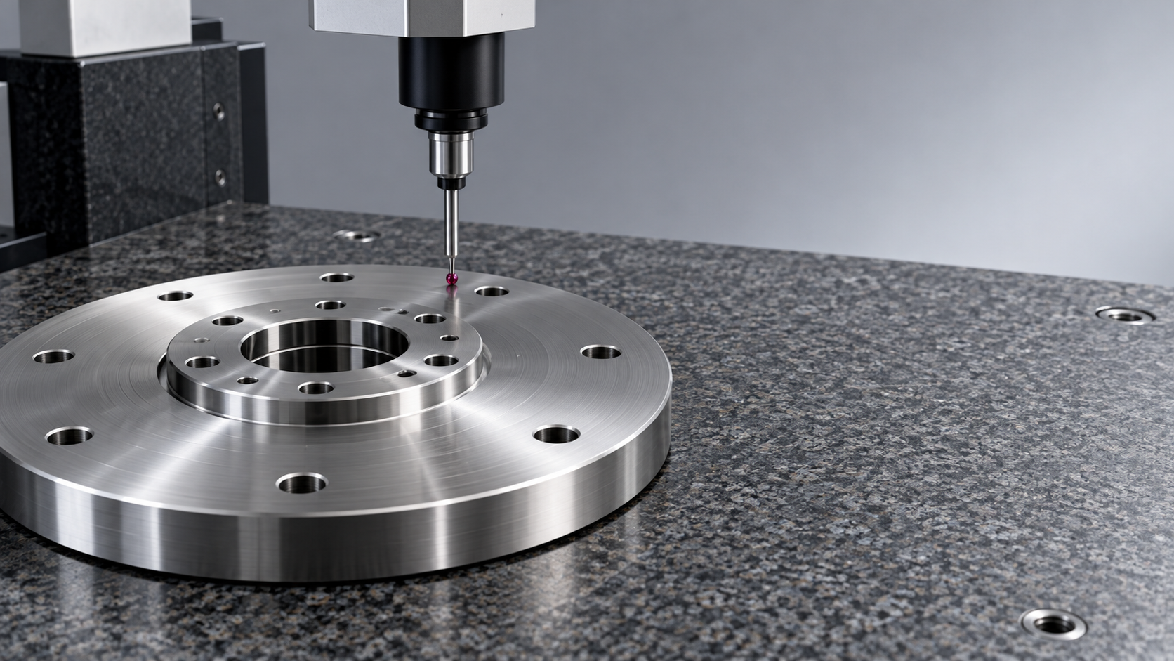
The last point deserves more attention than it usually receives. Large parts are expensive to move, and some geometry is best verified while the workpiece remains clamped. On-machine probing does not replace final inspection, but it can detect a setup issue before finishing operations are completed. Where tolerances are especially demanding, the measurement strategy should be discussed at the same time as the cutting strategy.
Avoid selecting solely by maximum capacity
A machine with a very large table or oversized swing can look like the safest option. Sometimes it is. But unused capacity can create its own inefficiencies: longer loading distances, reduced accessibility for smaller parts, higher energy demand, and a larger installation footprint. More importantly, a machine may fit the workpiece physically while still being poorly suited to its cutting forces, required precision, automation needs, or tool-change frequency.
The better comparison is between usable capacity and process capability. A project manager should ask whether the proposed machine can complete the highest-risk operations confidently, not whether it can accommodate the largest theoretical workpiece.
Planning for Lead Time, Integration, and Shop Reality
Heavy machining projects frequently slip before the first chip is cut. Foundation preparation, electrical supply, coolant management, lifting equipment, machine acceptance, fixture design, tooling procurement, and operator training can all affect readiness. A sophisticated CNC platform is not an isolated asset; it has to fit the physical and digital environment around it.
Digital integration is increasingly relevant here. Modern machine tool environments can connect CNC data, tool-life information, probing results, maintenance records, and production scheduling. For a large-component project, this is most useful when it supports real decisions: identifying an overloaded spindle, tracking a recurring tooling issue, preserving setup data for repeat orders, or coordinating a machine with an automated production line. Collecting data without a clear use case only adds another system for the team to maintain.
Supply-chain support should also be reviewed early, particularly for specialized rotary tables, large steady rests, custom fixtures, cutting tools, and control-system options. Machine tool manufacturing is supported by strong industrial clusters in regions such as China, Germany, Japan, and South Korea, alongside suppliers operating across international markets. That range gives buyers options, but it also makes technical alignment essential. Documentation, service response expectations, spare-part availability, control compatibility, and commissioning responsibilities should be clarified before the equipment becomes critical to a delivery date.
A More Reliable Path to Heavy Machining Projects
The most reliable heavy-machining projects begin with a practical review of the part, not an abstract machine comparison. Start with the heaviest and most unstable incoming condition. Map the datum scheme, lifting points, clamping surfaces, roughing allowance, finishing requirements, and inspection sequence. Then identify the operations where a loss of rigidity, thermal movement, or re-clamping error would be most expensive.
That exercise often reveals whether the right answer is a vertical turning platform, a horizontal boring machine, a gantry system, a multi-axis machining center, or a combination of equipment. It may also show that the project needs better fixturing, a revised part orientation, or an earlier stress-relief step more urgently than it needs a larger machine.
A heavy duty machine tool is valuable because it provides the stability and controlled power needed for demanding components. Its full value appears only when the machine, workholding, tooling, handling, programming, and measurement plan are developed together. For large industrial parts, that integrated approach is usually what protects lead time, quality, and the project team’s margin for error.
Recommended for You
![]() Mitsubishi Electric Announces Physical AI System Linking Humanoid Robots and CNC MachinesMachine Tool Industry Editorial Team
Mitsubishi Electric Announces Physical AI System Linking Humanoid Robots and CNC MachinesMachine Tool Industry Editorial Team Precision Machining for Defense: Supplier Quality and Traceability ChecksManufacturing Market Research Center
![]() Nidec Machine Tool Launches MVR-5X Five-Axis Gantry MachineMachine Tool Industry Editorial Team
Nidec Machine Tool Launches MVR-5X Five-Axis Gantry MachineMachine Tool Industry Editorial Team Choosing a Precision Disc Parts Manufacturer in China: Tolerances and Quality ChecksManufacturing Market Research Center
![]() Siemens Executive Says AI Could Raise Factory Automation to 80%Manufacturing Market Research Center
Siemens Executive Says AI Could Raise Factory Automation to 80%Manufacturing Market Research Center Choosing Automated Machine Tools for High-Mix, Low-Volume ProductionMachine Tool Industry Editorial Team


Aris Katos
Future of Carbide Coatings
15+ years in precision manufacturing systems. Specialized in high-speed milling and aerospace grade alloy processing.
▶
Choosing a CNC Machine for Mold Making: Accuracy, Rigidity, and Surface FinishCNC Machining Technology Center▶
How to Cut CNC Machining Energy Use per Part Without Longer Cycle TimesCNC Machining Technology Center▶
Will a Mazak CNC retrofit work with your existing servo drives?CNC Machining Technology Center▶
Do energy-efficient machine tools reduce power use at partial load?CNC Machining Technology Center▶
Comparing energy-efficient machine tools by energy use per partCNC Machining Technology Center
▶
Mastering 5-Axis Workholding Strategies
Join our technical panel on Nov 15th to learn about reducing vibrations in thin-wall components.

Providing you with integrated sanding solutions
Before-sales and after-sales services
Comprehensive technical support