• Global CNC market projected to reach $128B by 2028 • New EU trade regulations for precision tooling components • Aerospace deman
NYSE: CNC +1.2%LME: STEEL -0.4%

How 5 Axis Machining Improves Accuracy and Surface Finish in Impeller Manufacturing
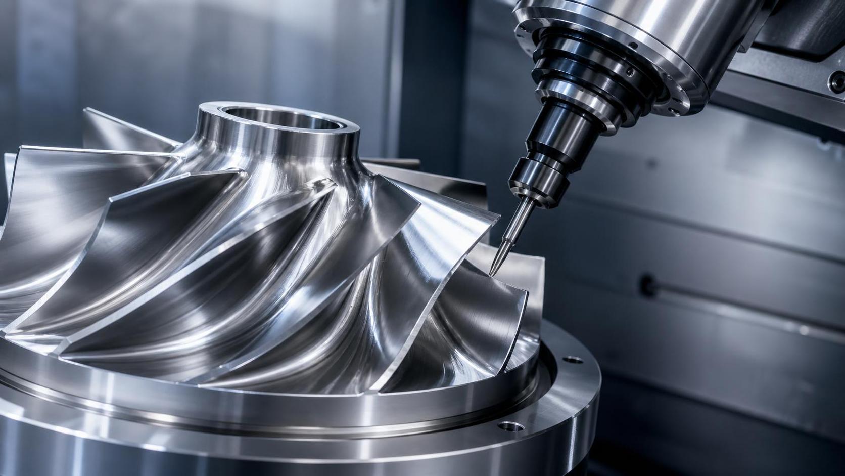
For technical evaluators assessing advanced turbine component production, 5 Axis Machining for impeller manufacturing offers a clear advantage in both dimensional accuracy and surface quality. By enabling continuous tool engagement on complex curved blades, it reduces repositioning errors, improves consistency, and minimizes secondary finishing. This makes it a critical solution for manufacturers seeking tighter tolerances, better aerodynamic performance, and more efficient production of high-precision impellers.
That advantage, however, should not be reduced to a simple claim that “more axes mean better parts.” In impeller manufacturing, accuracy and surface finish depend on how the machine kinematics, CAM strategy, tool design, material behavior, and inspection method work together. Technical evaluation therefore needs to go beyond the machine brochure. The real question is whether a 5-axis process can control the specific error sources that matter in thin blades, deep channels, tight hub geometries, and demanding flow-path surfaces.
Why impellers expose the limits of conventional machining
Impellers are difficult not because they are merely “complex parts,” but because their geometry forces several manufacturing problems to appear at the same time. Blade surfaces are twisted and freeform. Passage spacing is narrow. Blade thickness may be small relative to diameter. Surface transitions near the hub and shroud often require uninterrupted smoothness rather than a sequence of flat approximations. In many applications—especially aerospace, turbo machinery, energy equipment, and high-speed rotating systems—small geometric deviations can affect flow efficiency, vibration behavior, balance, and service life.
With 3-axis machining, the tool usually approaches from limited directions. That creates two common consequences. One is repeated repositioning or additional setups to access different blade areas. The other is less favorable tool contact on steep or undercut regions, which tends to increase scallop variation, chatter risk, and local overcut or undercut. Even when the final dimensions are technically within drawing tolerance, the surface may still show witness marks, inconsistent texture, or edge conditions that require extensive polishing.
This is where 5-axis capability changes the manufacturing logic. It is not only about reaching more surfaces. It is about controlling the angle between tool and workpiece continuously so the effective cutting conditions remain stable across a highly curved geometry.
How 5-axis machining improves dimensional accuracy
The biggest accuracy gain in impeller production often comes from reducing error accumulation. Each manual or indexed repositioning step introduces potential offsets: fixture variation, datum transfer error, rotary axis misalignment, probing uncertainty, and operator-dependent setup differences. On parts with multiple blades and narrow channels, these small deviations can become visible as blade-to-blade inconsistency.
5-axis machining reduces that chain of errors by allowing more of the part to be completed in a single setup. For technical evaluation, this matters more than the abstract axis count. A stable one-setup or near-one-setup process improves positional coherence between hub, blades, and outer profile. The result is usually better blade spacing consistency, more reliable profile conformity, and reduced mismatch at surface intersections.
There is another accuracy benefit that is easy to overlook: tool orientation control. On freeform surfaces, the contact point on a ball nose or tapered tool strongly influences the effective cutting radius. If the machine can continuously tilt the tool, the CAM system can keep the contact zone in a more favorable region of the cutter. That reduces rubbing, limits abrupt load changes, and helps maintain predictable geometry along the blade surface.
In practice, better accuracy in 5-axis impeller machining is often visible in:
- more consistent blade profile from root to tip;
- lower mismatch between adjacent toolpath regions;
- improved control of hub-blade blend areas;
- reduced distortion risk on thin sections due to more stable cutting engagement;
- better repeatability across batches, especially where multiple identical impellers are required.
That said, a 5-axis machine does not eliminate geometric error by itself. Rotary axis calibration, volumetric compensation, thermal stability, spindle condition, and fixture rigidity remain decisive. A poorly calibrated 5-axis machine can produce errors that are harder to diagnose than those from a simpler setup.
Surface finish improves because the cut becomes more controlled, not merely finer
Surface finish on an impeller is not just a cosmetic issue. It can affect aerodynamic or hydraulic efficiency, fouling tendency, cavitation behavior in fluid systems, and the amount of post-processing needed before balancing or coating. In many technical reviews, the mistake is to discuss finish only in terms of Ra. For impellers, evaluators should also consider directional lay, waviness, blend smoothness, and localized tool marks in the flow path.
5-axis machining improves finish primarily through better tool engagement. When the cutter can tilt continuously, the process can avoid cutting with the tool tip dead center, where surface speed is low and rubbing is more likely. The machine can also maintain more uniform step-over and contact conditions over steep blade curvature. This generally reduces scallop inconsistency and produces a more even surface pattern.
The improvement is especially notable in five situations:
- Deep channels: Tool access is better, so long overhang tools can sometimes be avoided or used more effectively.
- Twisted blades: Smooth orientation changes reduce abrupt transitions between adjacent passes.
- Thin blade edges: Better control of cutting direction helps reduce burr formation and edge damage.
- Hub blends: Multi-axis interpolation supports cleaner surface continuity where several curvatures intersect.
- Hard-to-machine alloys: Stable engagement lowers the chance of work hardening, smearing, or heat-related surface defects.
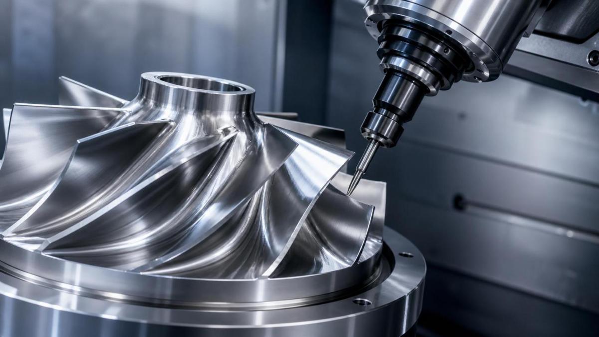
In real production, the best surface quality gains often come from semi-finishing and finishing strategy rather than roughing. If the semi-finish stage leaves a uniform stock condition on every blade surface, the final pass can perform much more consistently. This is one reason why CAM process design is central to any evaluation of 5-axis performance.
The machine alone does not define the result
Buyers and evaluators often focus heavily on the machining center specification: swivel range, spindle speed, rapid traverse, and control brand. Those are relevant, but impeller quality is strongly process-dependent. A supplier with an average machine and a mature toolpath strategy may outperform a supplier with a high-end machine but weak programming and verification practices.
Several technical factors should be reviewed before concluding that 5-axis capability will deliver the required gains.
Kinematic configuration
Table-table, head-table, and head-head configurations behave differently in terms of stiffness, accessibility, part weight handling, and dynamic response. For small to medium impellers, a trunnion-style machine may offer excellent flexibility. For larger or heavier workpieces, configuration choice can affect not only access but also positional stability during simultaneous motion.
CAM strategy and collision management
Impeller machining relies heavily on advanced CAM functions: flank milling options, morphing toolpaths, swarf-style strategies where applicable, tool axis smoothing, and reliable gouge avoidance. Poorly optimized 5-axis paths may introduce overtravel, erratic feed changes, or unnecessary rotary motion, all of which can hurt surface finish.
Cutting tool selection
Barrel tools, lens tools, tapered ball end mills, and optimized small-radius finishing tools can significantly change both cycle time and finish quality. In some finishing applications, barrel-type tools allow larger effective contact width while maintaining a low cusp height, which can improve surface quality and reduce machining time. Whether that is suitable depends on blade geometry and accessibility.
Workholding and datum strategy
Because impellers often have demanding concentricity and profile relationships, fixture design should preserve rigidity without blocking tool access. Technical evaluation should review how the supplier establishes and verifies datums, especially if rough and finish operations are separated.
Thermal and dynamic stability
Long simultaneous 5-axis finishing cycles can be sensitive to spindle growth, rotary axis heat, and dynamic vibration. This becomes more important in titanium, nickel alloys, and stainless steels, where cutting loads and heat generation are harder to control than in aluminum.
Accuracy claims should be tied to measurable inspection logic
One recurring problem in supplier evaluation is that “high precision” is presented without a matching inspection method. Impeller geometry cannot be judged reliably by a few caliper points or standard CMM features alone. The inspection plan should reflect the actual function of the part.
For technical evaluators, useful review points include:
- blade profile deviation measurement against CAD model;
- blade-to-blade variation analysis;
- hub and shroud runout checks;
- surface roughness measurement at functionally relevant flow-path locations;
- verification of blend continuity rather than isolated point accuracy;
- balancing implications after machining and any manual finishing.
In higher-end applications, optical scanning or specialized 3D inspection routines may be used alongside CMM measurement. The key issue is traceability between machining strategy and quality data. If a supplier reports excellent average roughness but still relies on heavy manual polishing to remove tool marks, the final geometry may no longer fully reflect the machined profile. That should be treated as a process risk, not a cosmetic detail.
Where 5-axis machining creates the most value in impeller manufacturing
The strongest case for 5-axis machining is not universal; it is greatest where geometric complexity and quality sensitivity are both high. Closed impellers, high-speed compressor impellers, turbocharger components, aerospace turbine-related flow parts, and precision pump impellers are typical examples. In such parts, dimensional deviations and poor finish can directly affect efficiency, noise, vibration, or downstream assembly performance.
For simpler open impellers with less demanding blade geometry, a 3+2 or well-optimized 3-axis process may still be economically reasonable. This is an important evaluation point because not every impeller needs full simultaneous 5-axis machining. In some cases, roughing may be done with indexed positioning while finishing critical blade surfaces uses simultaneous motion. The decision should follow geometry, tolerance stack-up, required finish, material, and batch size—not the desire to use the most advanced process available.
Common misconceptions during technical evaluation
One misconception is that 5-axis automatically means tighter tolerance. In reality, the process can improve tolerance capability, but only when machine calibration, programming quality, and process control are mature.
Another is that better surface finish always means slower machining. In many impeller applications, the opposite can be true. A more efficient tool orientation and advanced cutter geometry can produce a better finish with fewer passes or less manual rework.
A third misconception is that post-polishing is harmless. Light finishing may be acceptable depending on specification, but aggressive manual polishing can round edges, alter blade thickness, and reduce profile fidelity. For flow-sensitive parts, the amount and control of manual intervention should be reviewed carefully.
It is also common to overemphasize spindle speed and ignore rotary axis behavior. On impeller surfaces, synchronized rotary motion quality can influence finish as much as spindle capability. Servo tuning, interpolation smoothness, and control look-ahead functions deserve attention.
What technical evaluators should verify before approving a process
A sound evaluation of 5 Axis Machining for impeller manufacturing should focus on evidence rather than machine labels. Ask to review representative parts with similar blade depth, material, and tolerance requirements. Compare the as-machined condition with the final delivered condition. Confirm how much manual blending is performed. Check whether the supplier can show repeatable inspection data across multiple parts, not just one successful sample.
It is also worth reviewing the digital thread behind the process: CAD-to-CAM continuity, simulation for collision and overtravel avoidance, post-processor reliability, in-process probing, and change control when the tool or setup is modified. In complex impeller work, many quality escapes originate from process translation errors rather than from cutting limitations alone.
Where standards are concerned, the exact acceptance criteria depend on industry and end use. Surface texture evaluation may reference ISO 21920 series in current practice for profile texture characterization, while dimensional tolerancing may rely on drawing-specific GD&T requirements and customer standards. Material and sector-specific compliance can vary, so any mandatory requirement beyond the drawing should be treated as 【待核实】 unless clearly specified by the customer or applicable regulation.
The real advantage is process capability, not just machine sophistication
5-axis machining improves impeller accuracy and surface finish because it gives the process far better control over how the tool meets the blade surface. Fewer setups reduce accumulated error. Continuous orientation improves cutting stability. Better access and smoother interpolation produce more consistent flow-path quality. In demanding impeller applications, those improvements are often decisive.
For technical evaluators, the most useful conclusion is practical: the value of 5-axis machining should be judged as a process capability package. Machine architecture, CAM quality, tool strategy, fixturing, thermal control, and inspection discipline all determine whether the theoretical advantages become measurable production results. When those elements are aligned, 5-axis machining is not just a faster way to make impellers. It is a more reliable way to produce the geometry and surface integrity that high-performance rotating components actually require.
Recommended for You
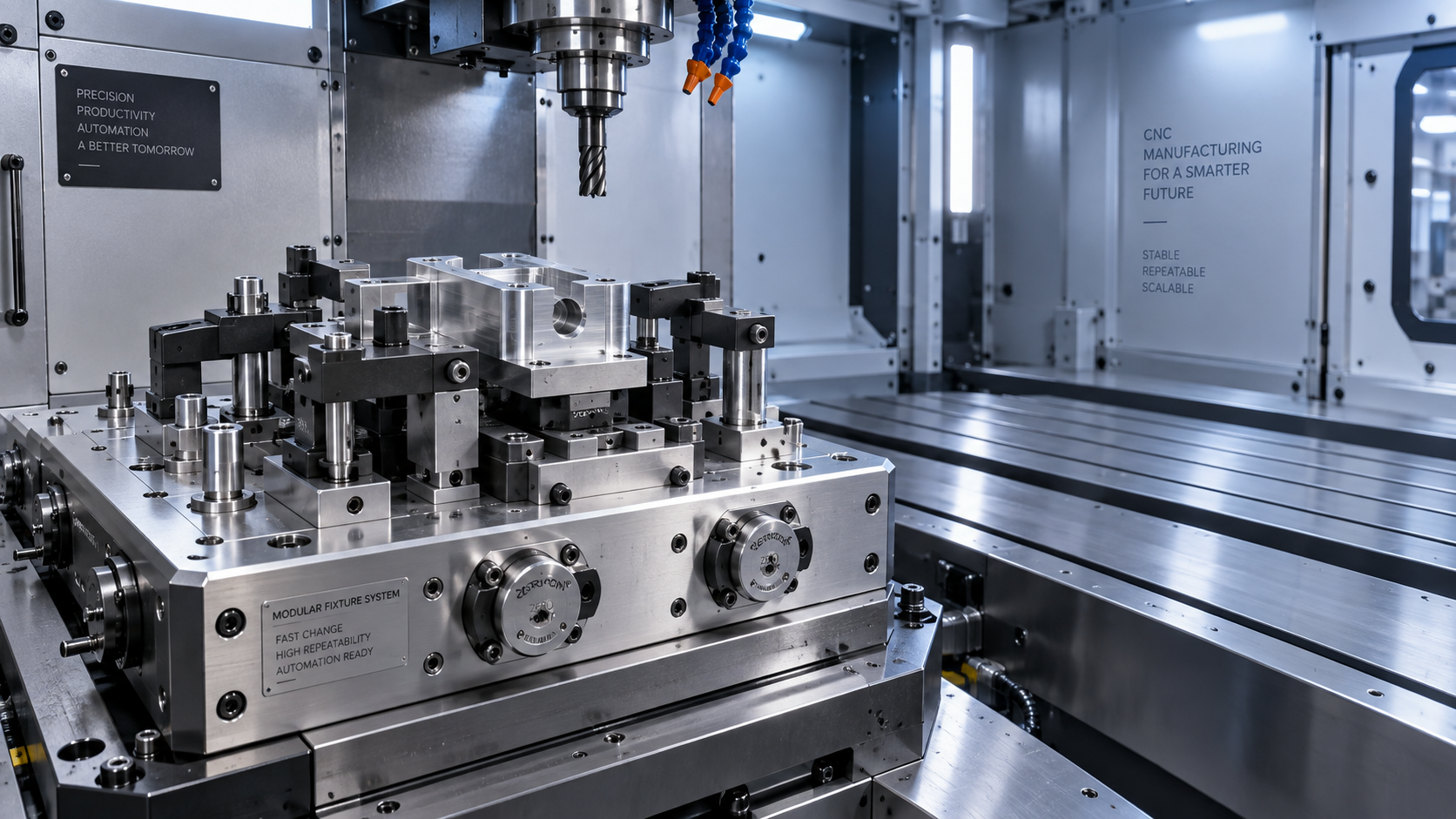
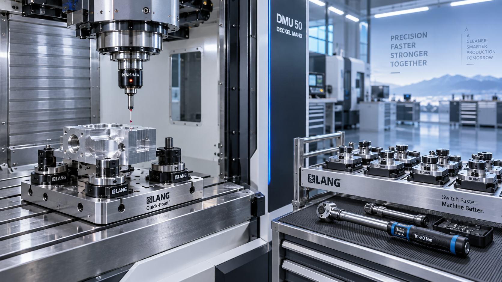
 Zero-Point Clamping or Modular Fixtures? Choosing a Faster CNC Changeover SystemCNC Machining Technology Center
 How to Cut CNC Fixture Changeover Time Without Sacrificing Part AccuracyCNC Machining Technology Center
 When Does CNC Turning Pay Off? A Break-Even Guide by Annual Part VolumeMachine Tool Industry Editorial Team
 Machine Tool Standards by Country: What Importers Must Verify Before PurchaseManufacturing Policy Research Center
 CNC Lathe Quick Installation Guide: Alignment Checks Before First Production RunCNC Machining Technology Center
 How to Select a CNC Lathe for Small Parts Without Sacrificing Accuracy or Cycle TimeCNC Machining Technology Center

Aris Katos
Future of Carbide Coatings
15+ years in precision manufacturing systems. Specialized in high-speed milling and aerospace grade alloy processing.
▶
How Automated Precision Machining Maintains Tolerance in High-Mix ProductionCNC Machining Technology Center▶
CNC Programming Explained: From CAD Models to Reliable Shop-Floor ToolpathsCNC Machining Technology Center▶
How Multi-Axis Machining Produces Complex Components With Fewer SetupsCNC Machining Technology Center▶
How Much Does CNC Programming Software Cost in 2026?CNC Machining Technology Center▶
CNC Machining Explained: Processes, Tolerances, and Parts It Can ProduceCNC Machining Technology Center
Mastering 5-Axis Workholding Strategies
Join our technical panel on Nov 15th to learn about reducing vibrations in thin-wall components.

Providing you with integrated sanding solutions
Before-sales and after-sales services
Comprehensive technical support