• Global CNC market projected to reach $128B by 2028 • New EU trade regulations for precision tooling components • Aerospace deman
NYSE: CNC +1.2%LME: STEEL -0.4%

How to Evaluate a Heavy Duty Machine Tool for Large-Part Machining?
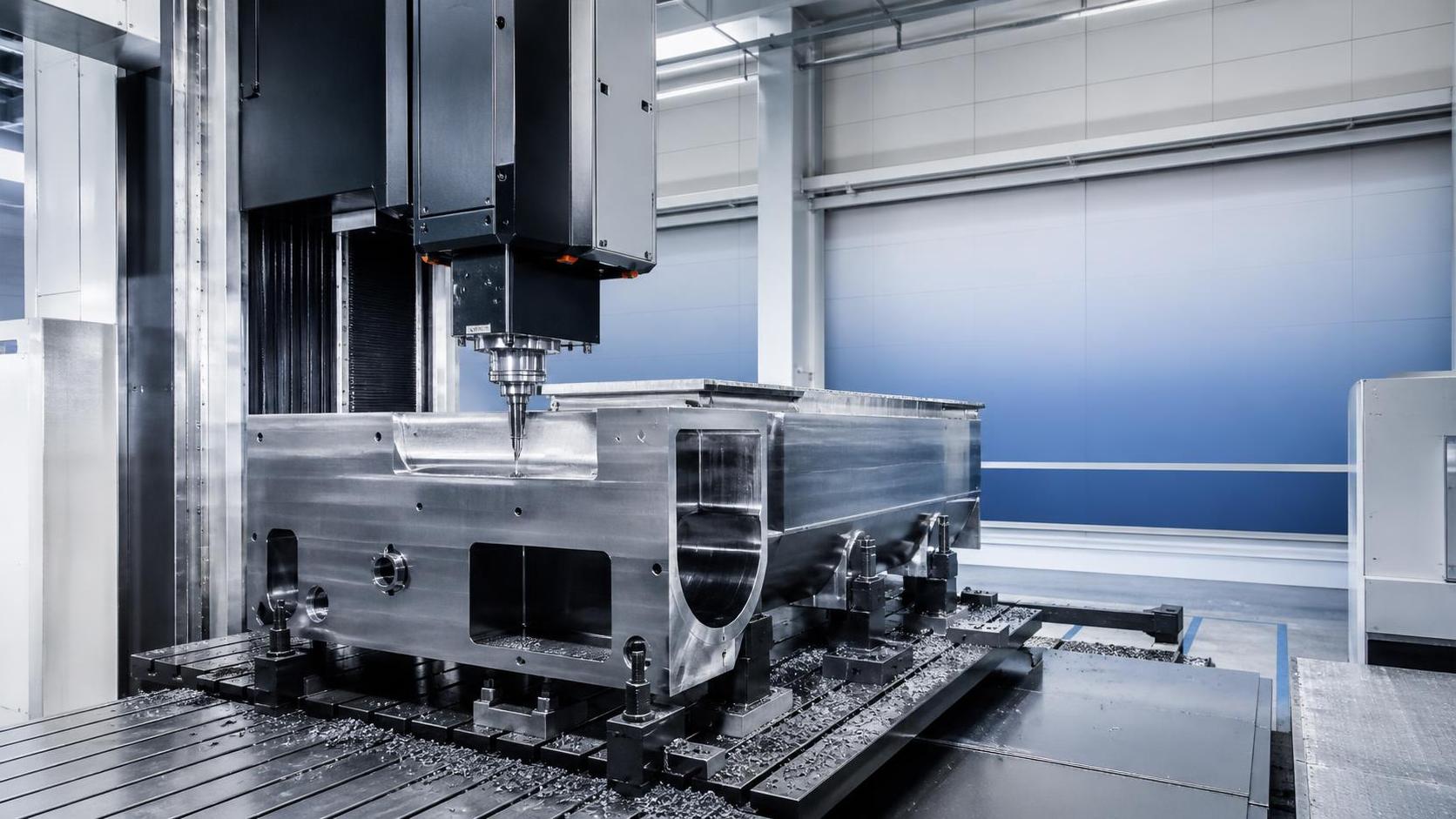
It often starts with a deceptively simple request: a larger workpiece is coming, the current equipment is near its limit, and someone asks whether a new machine can “handle it.” On paper, several models may seem suitable. They all list a large table, a high spindle power rating, and an impressive maximum load. But when the part is long, heavy, difficult to clamp, and expected to hold tight tolerances over long machining cycles, those headline numbers stop being enough.
Many people run into this when evaluating a heavy duty machine tool for large-part machining. The difficulty is not just choosing the biggest machine available. A poor evaluation can lead to chatter, thermal drift, awkward loading, poor chip evacuation, difficult maintenance access, or a machine that is technically capable but inefficient for the real process. The problem becomes more serious when the parts are expensive, the setup time is long, and each interrupted cycle wastes both material and schedule.
If you are comparing options and finding that brochures all look similar, the practical way forward is to shift the evaluation from machine size to process fit. The useful questions are less about maximums and more about how the machine behaves under your actual cutting conditions, with your actual part geometry, support method, tooling plan, and production rhythm.
Start from the part, not the catalog
A common mistake is to begin with the machine’s travel and swing, then try to fit the process into those numbers. For large-part machining, it is usually more reliable to begin with the part drawing, routing, and expected variation across jobs.
Look at the features that drive machine demand:
- Overall dimensions are only the starting point. Overhangs, awkward mass distribution, and thin-wall sections often matter more.
- Material type affects not just cutting power but heat generation, tool wear pattern, and vibration behavior.
- Tolerance zones should be separated by feature type. Flatness, roundness, bore position, and surface finish do not stress the machine in the same way.
- The number of setups changes the evaluation. A machine that reduces repositioning may outperform a larger one with less accessible geometry.
- Batch pattern matters. One-off heavy parts call for flexibility and setup support, while repeated jobs may justify dedicated fixturing and automation interfaces.
When this first step is skipped, evaluators often overvalue nominal machine capacity and undervalue workholding stability, axis configuration, and accessibility. Large-part machining exposes these gaps quickly.
Rigidity is not a single specification
Suppliers often describe rigidity in broad terms, but for selection work, rigidity should be broken into where it matters in the cut. A heavy duty machine tool may look structurally massive and still behave differently depending on ram extension, spindle head position, table location, or crossrail height.
Ask where the machine is most vulnerable during your planned operations. A boring pass deep inside a large housing places different demands on the structure than face milling a broad flange. If the process includes interrupted cuts, heavy roughing, or long tools, rigidity assessment becomes even more important.
Useful evaluation points include the bed and column construction, support span, guideway design, ram dimensions, and how stiffness changes across the working envelope. It also helps to review whether the machine relies on its best performance near the center of travel while your part forces cutting near the extremes. That mismatch is easy to miss in early comparison rounds.
For practical review, map major operations against likely machine postures. If several critical cuts happen in less stable positions, the machine deserves closer scrutiny even if its rated capacity appears generous.
Load capacity should include the setup, not just the part weight
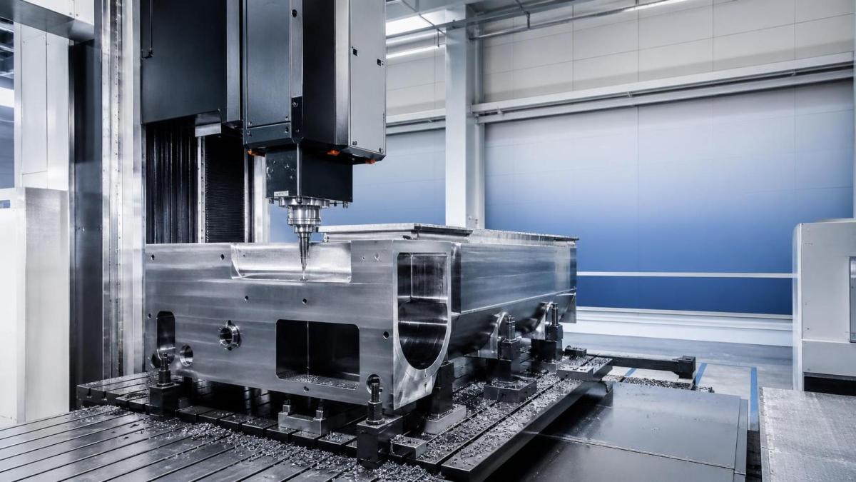
Large-part projects frequently underestimate total mass on the machine. The workpiece may be within the stated table load, but the fixture, support blocks, rotary attachments, balancing elements, or tailstock arrangement can change the picture significantly. In some cases, weight distribution matters more than total weight.
That is why static load figures are only the first checkpoint. You also need to examine:
- How the machine handles eccentric loading
- Whether the table or axis support is sensitive to off-center mass
- The effect of clamping force on thin or distorted castings
- Dynamic loads created during acceleration, deceleration, and heavy cutting entry
For turning applications, chuck size and spindle torque are not enough by themselves. Review the bearing arrangement, support method for long shafts, and the implications of imbalance at operating speed. For milling or boring, consider whether fixture height pushes the cutting point farther from the table than expected, which can amplify vibration.
In other words, machine loading should be evaluated as a system condition, not a line-item number.
Accuracy retention matters more than no-load accuracy
It is easy to focus on initial positioning accuracy because it is a familiar comparison point. But in large-part machining, many real problems appear after the machine has been cutting for a while. Heat builds up, the part absorbs energy unevenly, chips accumulate, and long travel axes are used repeatedly. This is where accuracy retention becomes more meaningful than a clean specification measured under limited conditions.
When comparing machines, try to understand how they maintain precision during extended operation rather than just at startup. Questions worth asking include whether thermal compensation is available, how temperature-sensitive components are arranged, and how lubrication and cooling systems influence long-cycle behavior.
If your process includes large castings, weldments, or energy equipment components, a slight drift over time can create rework far from the original cut location. That risk is often underestimated during purchase discussions because the machine may still appear highly accurate in a short demonstration.
Thermal behavior can decide whether the machine is usable for fine finishing
A machine intended for roughing heavy stock removal is not automatically a good finishing platform for the same part. In many shops, one source of frustration is finding that the machine has enough power and envelope but struggles to keep geometry stable once the cutting cycle becomes long and heat distribution changes.
Thermal stability should be reviewed from several angles: spindle heating, hydraulic or lubrication heat sources, coolant management, ambient sensitivity, and axis drive behavior over repeated traverses. The machine layout also plays a role. Symmetry, separation of heat-generating components, and structural mass distribution can influence how predictable thermal movement becomes.
This does not mean every application needs the same level of thermal control. If the part has large tolerance bands and is mainly a roughing job, the threshold is different. But if one machine is expected to rough, semi-finish, and finish large structural parts in the same environment, thermal behavior deserves much more weight in the decision.
Spindle power is only useful when matched to the process window
One of the most common evaluation errors is assuming that higher spindle power automatically means better suitability. In practice, the question is whether the machine can deliver stable torque and cutting performance where your tools will actually run.
For large diameters and heavy stock removal, low-speed torque may matter more than top-end spindle speed. For boring work with long tools, smooth power delivery and vibration control may matter more than headline horsepower. For mixed-part environments, the machine needs a usable operating window rather than one strong point that looks impressive in comparison tables.
It helps to review the intended tooling package at the same time as the machine. Toolholder type, available cutter diameters, extension lengths, and insert strategy all influence whether the spindle characteristics fit the job. Evaluating the machine without the tooling plan often creates a misleading sense of compatibility.
Workholding and access usually expose hidden problems early
Large parts rarely fail in planning because the machine is too small. More often, they fail because loading is slow, clamping is awkward, crane access is restricted, or operators cannot safely reach critical setup points. These practical details do not always appear in standard technical summaries, yet they strongly affect whether the machine will perform well in day-to-day use.
During evaluation, consider the path the part must take from staging area to machine position. Check whether doors, guarding, rotary ranges, tailstock movement, or headstock design make setup harder than expected. Review where probes, steady rests, support rollers, fixtures, and chip conveyors sit in relation to the operator’s working space.
If the machine suits the cut but complicates every setup, the real cost appears later in lost time, setup variation, and increased risk of handling damage.
Automation and digital integration should be judged by real need
In some selection discussions, automation features receive too much attention because they sound future-proof. In others, they are ignored until late, when it becomes clear the machine must connect with existing systems. A balanced approach is better.
For large-part machining, relevant questions are usually straightforward: can the machine support probing, tool monitoring, offset management, condition monitoring, and data collection in a way that fits your process? If pallet systems, robotic loading, or flexible production links are being considered, do they genuinely suit the part size and changeover pattern?
Not every heavy machine needs advanced automation from day one. But basic compatibility with measurement systems, fixture identification, and production data flow can make future changes less disruptive. The goal is not to buy every available feature. It is to avoid selecting a machine that becomes isolated the moment your process grows more controlled or more connected.
Maintenance access and serviceability belong in the technical review
This part is often left to later discussions, yet it affects uptime as directly as cutting performance. Large machines may require access to guideways, lubrication points, spindle areas, hydraulic units, and chip systems that are more difficult to reach than on smaller equipment. If service tasks are awkward, they tend to be delayed, and delayed maintenance on a large machine can quickly turn into accuracy or reliability problems.
Ask practical questions: how accessible are key wear components, how are chips removed from deep or enclosed zones, how easy is it to inspect alignment-sensitive areas, and what support is needed for preventive maintenance? Even if two machines offer similar cutting capability, the easier one to maintain may be the safer long-term choice.
A better comparison method is to score process risk, not just machine features
When several machines appear technically qualified, feature-by-feature comparison stops being very helpful. At that point, it is often better to compare them against process risks. For example:
- Which machine is least likely to lose stability during long roughing passes?
- Which one keeps the cutting zone most accessible for setup verification?
- Which option places the fewest limits on future part families with similar size but different geometry?
- Which machine creates the smallest gap between roughing capability and finishing control?
This way of thinking helps avoid a common trap: selecting the machine that looks strongest in isolated specifications but creates more uncertainty in real production. A heavy duty machine tool should be judged by how predictably it supports the intended workflow, not just by its maximum envelope or motor rating.
When the choice is still unclear
If two or three options remain close after technical review, return to the parts that are hardest to machine and build the decision around them. The difficult features usually reveal the right answer faster than average operations do. It is also worth checking whether the machine can support reasonable process adjustments without becoming unstable, such as different fixture heights, alternate tool paths, or revised cutting sequences.
That flexibility matters because large-part machining rarely stays identical from one job to the next. The best choice is often not the machine that looks perfect for one drawing, but the one that remains dependable across the variations that are likely to appear.
In the end, evaluating a machine for large-part work is less about finding the largest platform and more about understanding behavior under load, over time, and through the full setup-to-finish cycle. If you anchor the review in actual part demands, cutting posture, thermal control, workholding reality, and serviceability, the decision becomes much clearer—and far less dependent on brochure language.
Recommended for You
 How to Select CNC Equipment for High-Mix, Low-Volume ProductionCNC Machining Technology Center
 Can CNC Machining Inconel Control Tool Wear in High-Temperature Aerospace Parts?CNC Machining Technology Center
 Machine Tool Market Outlook: Demand Drivers, Capacity Shifts, and Investment RisksManufacturing Market Research Center
 Zero-Point Clamping or Modular Fixtures? Choosing a Faster CNC Changeover SystemCNC Machining Technology Center
 How to Cut CNC Fixture Changeover Time Without Sacrificing Part AccuracyCNC Machining Technology Center
 When Does CNC Turning Pay Off? A Break-Even Guide by Annual Part VolumeMachine Tool Industry Editorial Team

Aris Katos
Future of Carbide Coatings
15+ years in precision manufacturing systems. Specialized in high-speed milling and aerospace grade alloy processing.
▶
How to Select CNC Equipment for High-Mix, Low-Volume ProductionCNC Machining Technology Center▶
Can CNC Machining Inconel Control Tool Wear in High-Temperature Aerospace Parts?CNC Machining Technology Center▶
How Automated Precision Machining Maintains Tolerance in High-Mix ProductionCNC Machining Technology Center▶
CNC Programming Explained: From CAD Models to Reliable Shop-Floor ToolpathsCNC Machining Technology Center▶
How Multi-Axis Machining Produces Complex Components With Fewer SetupsCNC Machining Technology Center
Mastering 5-Axis Workholding Strategies
Join our technical panel on Nov 15th to learn about reducing vibrations in thin-wall components.

Providing you with integrated sanding solutions
Before-sales and after-sales services
Comprehensive technical support