• Global CNC market projected to reach $128B by 2028 • New EU trade regulations for precision tooling components • Aerospace deman
NYSE: CNC +1.2%LME: STEEL -0.4%

How to Evaluate a Multi-axis Machining Center for Complex Parts and Tight Tolerances
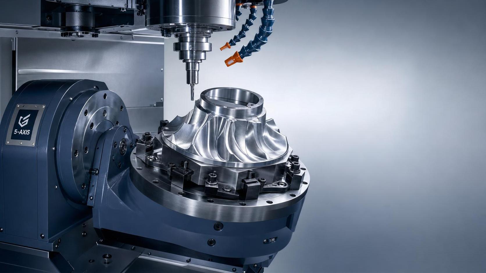
What a Multi-axis Machining Center Must Prove Before It Earns a Place on a Tight-Tolerance Job
The easiest mistake in evaluating a Multi-axis Machining Center for Complex Parts is to treat the machine as a specification sheet. Axis count, spindle speed, tool magazine size, rapid traverse: all of those matter, but none of them tells you whether the machine will actually hold a demanding aerospace bracket, a turbine-related feature, a thin-wall housing, or a precision structural component within tolerance over a full shift. For technical evaluators, the real question is not whether a machine can move in five axes. It is whether it can do so repeatedly, under load, with controlled geometry, stable heat behavior, predictable probing, and enough process margin that production does not turn into constant correction.
That is why a serious evaluation usually starts by reframing the purchase question. You are not selecting a machine in the abstract. You are selecting a process platform. A multi-axis center is only valuable when its kinematics, structure, control, spindle system, measurement routines, and fixturing logic fit the parts you actually intend to make. A machine that looks impressive in a showroom may still be the wrong choice for tight positional tolerances, difficult materials, or parts with deep cavities and compound-angle features.
Complex parts expose weaknesses quickly. Once simultaneous interpolation begins, small errors stop behaving like small errors. Rotary axis backlash, pivot-point misalignment, thermal drift, spindle growth, inadequate damping, and even control tuning can show up as mismatched surfaces, blend errors, poor true position, or unstable finish. On simpler three-axis work, some of those issues can be compensated manually. On complex five-axis machining, they tend to stack.
Start with the part family, not the machine brochure
A useful evaluation begins with a disciplined look at the part mix. Are you machining aluminum structural parts, titanium aerospace features, hardened steel molds, stainless medical components, or mixed-material production? The answer changes what “good” looks like. High-speed contouring in aluminum rewards acceleration, look-ahead control, and thermal predictability during long cycles. Titanium and nickel-based alloys place more emphasis on torque delivery, spindle rigidity, machine damping, and chip evacuation. Thin-wall parts raise concern about cutting forces and vibration control. Deep, obstructed geometries shift attention toward tool reach, collision avoidance, and trunnion or head-head accessibility.
This is also where many evaluations become too generic. A machine may be accurate in the sense that it passes acceptance tests, yet still be unsuited to your work envelope, tool lengths, table loading, or required angular approach paths. Tight-tolerance machining is not just a question of nominal machine accuracy. It is a question of accuracy at the part feature, with the actual fixture, actual tool stick-out, actual material removal rates, and actual cycle time expectations.
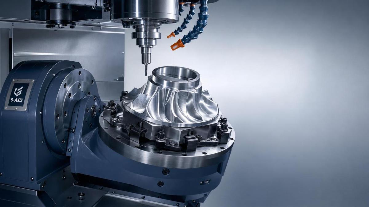
Accuracy is only useful if it survives motion, heat, and time
Machine builders often present positioning and repeatability values, but evaluators need to read those numbers carefully. Static axis accuracy does not fully describe volumetric accuracy across the working zone, and it says even less about dynamic behavior during simultaneous motion. For complex parts, the machine’s geometric integrity through coordinated linear and rotary movement matters more than one isolated axis value.
In practical terms, ask how the builder verifies rotary axis centerline accuracy, kinematic calibration, and thermal compensation. Ask how often recalibration is typically required in production environments. Ask what happens after warm-up, after heavy roughing, and after long finishing cycles. Machines intended for high-precision multi-axis work should show a coherent approach to thermal control, not just good numbers taken under ideal test conditions.
Thermal stability is frequently underestimated because it is less visible than spindle speed or axis travel. Yet on tight-tolerance parts, heat is often what separates acceptable first-piece results from reliable production capability. Growth in the spindle, rotary table, ballscrews, guideways, or machine structure can shift geometry enough to force offsets, frequent touch-offs, or increased scrap risk. A technically sound evaluation looks for a machine that reaches stable behavior predictably and maintains it with minimal intervention.
Rigidity is not a sales word; it is a surface finish and tolerance issue
For complex parts, rigidity is not limited to the cast base or column. It includes the entire force path: spindle interface, bearings, axis drives, rotary mechanisms, table structure, fixture support, and toolholder system. A machine can appear robust and still lose control when a long tool is cutting at an angle in a difficult material. That loss may show up as chatter, taper, inconsistent blend radii, or edge breakdown rather than a dramatic failure.
This is why trial cutting remains one of the most valuable selection tools when it is done honestly. Generic demo cuts do not reveal much. A representative test part, or at least representative features, gives a better read on vibration behavior, finish quality, feature-to-feature consistency, and real cycle performance. Even when a full benchmark part is not possible, evaluators should push for conditions that resemble actual production rather than polished demonstration routines designed to flatter the machine.
The rotary axes deserve more scrutiny than they usually get
When people discuss a Multi-axis Machining Center for Complex Parts, they often focus on the fifth axis as if its existence alone guarantees capability. In practice, the rotary architecture is one of the main determinants of success. A trunnion-style machine, a swivel head design, and a head-table configuration each bring different tradeoffs in accessibility, inertia, part weight handling, collision risk, thermal behavior, and accuracy retention under changing loads.
The evaluation should examine more than travel limits. How stiff are the rotary axes near extreme positions? What is the clamping behavior, if clamping is used? How well does the control manage interpolation through changing vector directions? Is there enough clearance for tools, probes, fixtures, and chip flow without forcing compromised setups? Some machines are very capable within a narrow sweet spot but become awkward or less stable once part size, fixture height, or tool reach increases.
Control quality matters more than many purchasing teams expect
The machine structure and spindle may receive most of the attention, but the CNC control and its implementation often determine whether complex toolpaths become smooth parts or inconsistent ones. Multi-axis machining depends heavily on interpolation quality, look-ahead capability, smoothing functions, jerk management, and the interaction between CAM output and machine kinematics. A poor match here can produce witness marks, slowdowns in dense toolpaths, or unexpected deviations on sculpted geometry even when the mechanical platform is sound.
That means evaluation should include the postprocessor path, probing cycles, tool center point control, and the ease of validating five-axis motion before cutting. If your team spends excessive time adjusting posts, chasing angular mismatch, or working around obscure control behavior, the machine may still cut parts, but it will consume engineering time that never appears in the capital equipment quote.
Do not separate machine selection from metrology and process control
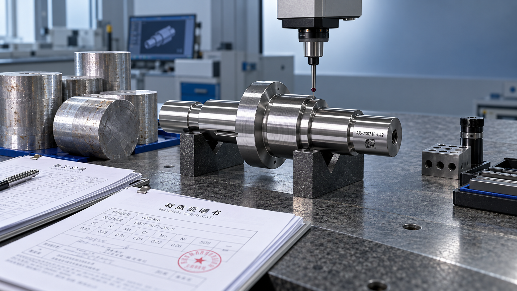
A machine intended for tight tolerances should be evaluated together with its measurement strategy. On-machine probing, tool measurement, broken-tool detection, and calibration routines are not accessories in this context. They are part of the machine’s practical capability. The tighter the tolerance stack, the less sense it makes to buy a multi-axis platform that depends on unstable manual setup methods or inconsistent external intervention.
There is also a boundary worth stating clearly: a high-end machine will not compensate for weak process discipline. If workholding distorts the part, if tooling is poorly matched, if coolant delivery is inadequate, or if CAM strategies are unstable, machine capability alone will not rescue the outcome. Good evaluators treat the machining center as one element in a controlled system, not a standalone cure for every precision problem.
Common misunderstandings during evaluation
One common misunderstanding is equating more axes with better accuracy. More axes expand access and reduce setups, but they also introduce more kinematic complexity. Unless the machine is well built, well calibrated, and well controlled, additional motion can create more opportunities for error.
Another is assuming that catalog precision values are directly comparable across builders without understanding the test basis. Acceptance methods, environmental assumptions, and reporting conventions vary. Technical evaluators should look beyond headline numbers and ask how the performance was established and under what conditions.
A third is underestimating service and support. For complex machining, downtime is not just lost spindle hours. It can mean interrupted qualification, delayed first-article approval, unstable calibration history, or extended troubleshooting between the machine supplier, CAM team, and cutting tool vendors. The quality of application support, spare parts availability, and local service competence belongs in the technical decision, not only the commercial one.
What a confident decision usually looks like
A sound decision is rarely based on the single “best” machine in generic terms. It is usually the machine that shows the clearest fit between part geometry, material behavior, tolerance demands, measurement routines, and production reality. That fit tends to reveal itself through evidence: representative cuts, stable thermal behavior, credible calibration practices, usable software integration, and a machine layout that does not force awkward compromises in fixturing or tool access.
When evaluating a Multi-axis Machining Center for Complex Parts, the most reliable mindset is cautious and specific. Ask what the machine can hold after hours of cutting, not only in a short demonstration. Ask how it behaves at full part envelope, not just near the center of travel. Ask how much engineering effort is required to keep it performing. In tight-tolerance work, that is where the true capability of the platform shows itself, and that is usually where the right buying decision becomes visible.
Recommended for You
![]() Zhongshan Xiaolan Machinery Exhibition Opens With Global Product DebutsMachine Tool Industry Editorial Team
Zhongshan Xiaolan Machinery Exhibition Opens With Global Product DebutsMachine Tool Industry Editorial Team Automated Production Machining: Which Parts and Batch Sizes Are a Good Fit?Machine Tool Industry Editorial Team
![]() FANUC Links FIELD System Data with Copilot to Advance Shop-Floor Data UseCNC Machining Technology Center
FANUC Links FIELD System Data with Copilot to Advance Shop-Floor Data UseCNC Machining Technology Center Smart Manufacturing for Aerospace: Building Traceability Across CNC OperationsCNC Machining Technology Center
![]() Mitsubishi Electric Announces Physical AI System Linking Humanoid Robots and CNC MachinesMachine Tool Industry Editorial Team
Mitsubishi Electric Announces Physical AI System Linking Humanoid Robots and CNC MachinesMachine Tool Industry Editorial Team Precision Machining for Defense: Supplier Quality and Traceability ChecksManufacturing Market Research Center


Aris Katos
Future of Carbide Coatings
15+ years in precision manufacturing systems. Specialized in high-speed milling and aerospace grade alloy processing.
▶
FANUC Links FIELD System Data with Copilot to Advance Shop-Floor Data UseCNC Machining Technology Center▶
Smart Manufacturing for Aerospace: Building Traceability Across CNC OperationsCNC Machining Technology Center▶
Choosing a CNC Machine for Mold Making: Accuracy, Rigidity, and Surface FinishCNC Machining Technology Center▶
How to Cut CNC Machining Energy Use per Part Without Longer Cycle TimesCNC Machining Technology Center▶
Will a Mazak CNC retrofit work with your existing servo drives?CNC Machining Technology Center
▶
Mastering 5-Axis Workholding Strategies
Join our technical panel on Nov 15th to learn about reducing vibrations in thin-wall components.

Providing you with integrated sanding solutions
Before-sales and after-sales services
Comprehensive technical support