• Global CNC market projected to reach $128B by 2028 • New EU trade regulations for precision tooling components • Aerospace deman
NYSE: CNC +1.2%LME: STEEL -0.4%

How to Optimize Stainless Steel Machining for Tool Life, Finish, and Cycle Time
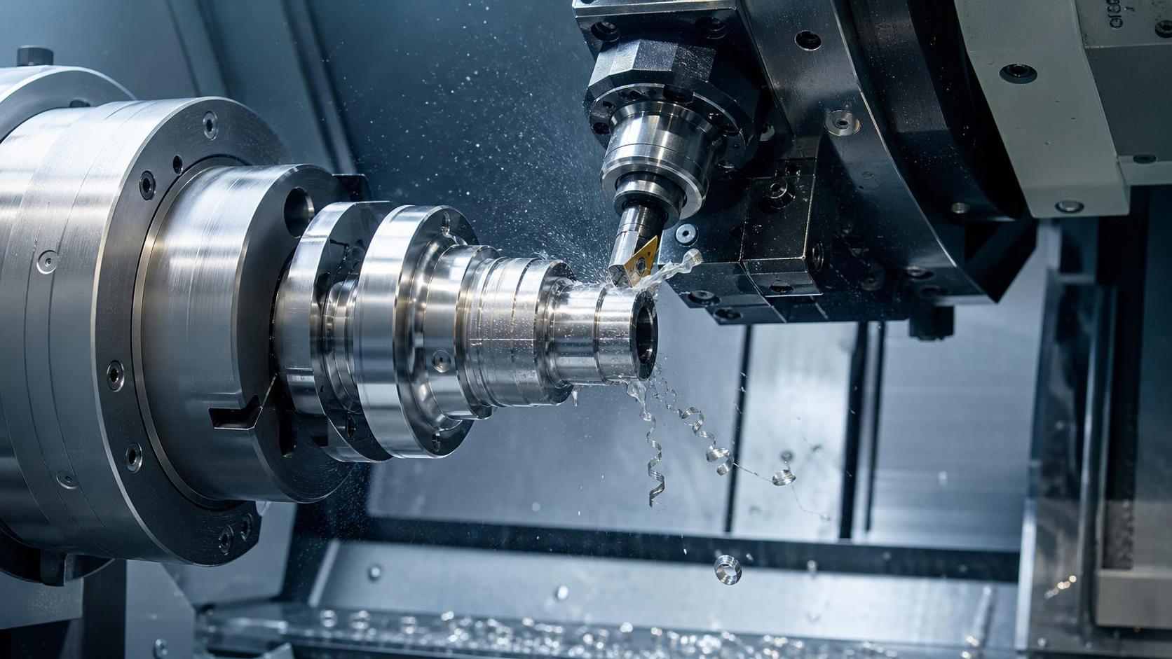
Stainless steel machining becomes unstable when heat stays in the cut, chips do not break cleanly, or the surface layer work-hardens before the next pass. Tool life then drops quickly, finish turns inconsistent, and cycle time rises because feeds must be reduced to keep the process under control. An effective machining route starts by separating stainless grades by behavior rather than by name alone: austenitic materials tend to smear and retain heat, ferritic grades are often easier to cut but can still gall, and duplex or precipitation-hardening variants usually demand tighter control of tool pressure, entry angle, and machine rigidity.
That distinction matters because the same spindle speed and insert style will not behave the same way across 304, 316, 420, or 17-4 class materials. A common error is to copy carbon steel parameters and only lower surface speed slightly. Stainless usually needs a more deliberate balance between edge strength and sharpness, with enough chip load to stay under the work-hardened layer but not so much that the edge micro-chips or the part deflects. If the process produces blue chips, polished wear lands, stringy nests, or a torn surface near the exit, the cutting zone is already signaling that the balance is off.
Start with the material condition, not the program
Before changing feeds and speeds, verify the incoming stock condition. Stainless bar, plate, forgings, and weldments can vary in scale, hardness spread, residual stress, and straightness. Annealed stock often allows a sharper edge and higher feed consistency, while cold-worked material may need a stronger geometry and lighter radial engagement to prevent chatter. Welded fabrications introduce another complication: the heat-affected zone can behave differently from the parent material, so a stable cut in one section may fail a few millimeters later.
Part geometry also changes the optimization logic. Thin walls, interrupted cuts, cross-holes, and long overhangs increase the need for controlled engagement. On deep pockets or long internal bores, chip evacuation may determine cycle time more than spindle power does. If chips recut, there is little value in increasing feed because edge damage and finish loss will force stoppages. At that point, the shortest cycle is often achieved by improving chip removal rather than by pushing the machine harder.
Tooling choices that actually change the result
Stainless steel often rewards tools with a sharp but supported edge. Inserts with heavy hone preparations survive impact, but they can raise cutting force and heat, especially in gummy austenitic grades. Highly positive geometries reduce force and improve finish, yet they may fail early if the setup has vibration or interrupted engagement. The right choice depends on whether the process limit is adhesion, notch wear, chipping, or deflection.
For turning, chipbreaker geometry is critical. A breaker designed for stainless should curl chips at moderate feed rates, not only at aggressive roughing conditions. If the chip only breaks when feed is pushed beyond the part's dimensional stability, the geometry is wrong for the job. Wiper inserts can improve finish without slowing the pass, but only when the holder, turret, and part support are rigid enough to keep the edge tracking correctly. On a flexible setup, a wiper may produce a paradoxical result: lower roughness in one area and waviness in another.
In milling, variable-pitch end mills and cutters with polished flute surfaces often help because they reduce chatter and limit material adhesion. Tool substrate and coating should be selected for heat and anti-welding behavior, not coating hardness alone. A very hard coating can still perform poorly if built-up edge forms repeatedly. Drill selection follows the same logic. Stainless drilling benefits from point geometry that centers reliably and evacuates chips before they compact in the flute. Through-coolant drills are often preferred on deeper holes because pecking can harden the hole wall and extend cycle time.
Tool projection deserves the same attention as grade and geometry. Excessive stickout lowers process stability faster than many parameter changes can recover. Shortening projection by even a modest amount may permit a higher feed, a better finish, and longer insert life at the same time. That is one of the few adjustments that can improve all three targets without a trade-off.
Cutting data should follow chip thickness, not catalog values alone
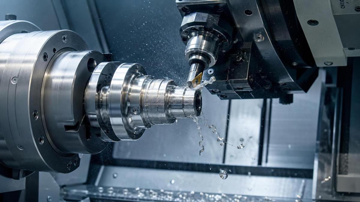
Published cutting data provides a starting band, but stainless responds strongly to actual chip thickness at the edge. In milling, radial step-over that is too small can thin the chip and encourage rubbing, even when the programmed feed per tooth appears correct. When chip thinning is present, feed often needs to be increased to maintain effective cutting. Without that correction, the edge runs hot, the workpiece skin hardens, and the next pass encounters a tougher surface than the previous one.
Turning has a related issue at shallow depth of cut. If the depth falls below the insert nose radius effect or below the hardened skin from the prior pass, the tool may slide rather than shear cleanly. The result is a bright but unstable surface, rapid flank wear, and dimensional drift as heat builds in the part. For finishing cuts, a smaller nose radius or a sharper finishing geometry can be more effective than simply reducing feed.
Cycle time should also be calculated across the whole operation, not per pass in isolation. An aggressive roughing cut that leaves heat in the part may force a pause before finishing or create thermal growth that needs compensation. A slightly lower roughing speed with better chip control sometimes shortens total machining time because finishing becomes predictable and offset corrections decrease.
Coolant strategy can determine whether the edge cuts or smears
Coolant application in stainless machining is not just a temperature issue. It affects lubrication at the edge, chip evacuation, thermal shock, and the tendency for chips to weld to the insert or cutter flute. Flood coolant can work well in open turning and light milling, but it becomes less effective when the fluid cannot reach the true cutting zone. In slots, deep cavities, or holemaking, pressure and direction matter more than volume alone.
Through-tool delivery is often the cleaner option for repeatability, especially where chips tend to pack. A broken stream or misaligned nozzle may leave one flute or one insert starved while the others cut normally, producing uneven wear that looks like a grade problem when it is actually a coolant access problem. In some interrupted milling cuts, dry or minimum-lubrication approaches may be considered if the tooling and machine enclosure support it, but the risk of adhesion and heat concentration has to be judged carefully. Switching between dry and wet mid-process is usually undesirable because thermal cycling can accelerate cracking.
Coolant concentration and cleanliness matter as well. Low concentration can reduce lubricity and encourage built-up edge. Dirty coolant carries fines back into the cut and can scratch a finish that otherwise looks acceptable under broad inspection. When finish requirements are tight, filtration condition becomes part of the machining process rather than a maintenance side note.
Machine and fixture behavior show up on the surface
Stainless magnifies small weaknesses in the machine system. Backlash, spindle runout, turret misalignment, weak clamping, or a worn chuck may remain hidden in easier materials and become visible immediately in stainless as chatter marks, taper, inconsistent burr formation, or edge breakdown. An Optimized Machining Process for stainless steel therefore depends on mechanical condition as much as on cutting theory.
Rigidity starts at workholding. Soft jaws should support the part with enough contact length to prevent micro-movement under load. On thin rings or tubes, clamping force that is too high can distort the part before the first cut begins, then release after machining and create false indications of tool wear or thermal growth. For milled components, fixture points should support the main cutting direction rather than simply restrain the part in a general sense. If the fixture allows the component to breathe during heavy roughing and then shift during finishing, no parameter adjustment will fully stabilize the result.
Toolholder connection quality is equally important. Collet wear, poor shrink-fit handling, and dirt on taper interfaces can introduce radial error that shortens tool life dramatically in stainless. In many shops, this appears first as inconsistent finish from one setup to another, even when the same program and tool are used. The root cause is often mechanical repeatability rather than the tool itself.
Programming methods that reduce heat and secondary damage
Toolpath design should avoid unnecessary dwell, abrupt engagement, and repeated air cuts disguised as caution. In milling, climb cutting is generally preferred for finish and edge life where setup rigidity allows it. Trochoidal or high-efficiency roughing can work well in stainless because it keeps radial engagement low and heat more manageable, but only if feed remains high enough to prevent rubbing. A low-feed adaptation of a dynamic toolpath usually loses the intended benefit.
Entry and exit moves deserve attention. Straight plunges with end mills in stainless can overload the center of the tool unless the geometry is built for it. Helical interpolation or ramping usually gives a cleaner entry. Likewise, pulling a tool directly out of a cut without smoothing the exit can leave burrs or witness marks that are later mistaken for finish issues. For turning, avoid dwelling at shoulders or diameters where heat can concentrate and notch wear can start.
Rest machining should be handled carefully. Leaving small islands of stock after roughing may create localized hard zones for the finishing tool. A more even stock allowance frequently gives better finish and better tool life than a path that appears shorter on screen. CAM efficiency is not always machining efficiency.
Signals that the process is drifting
Many stainless machining problems announce themselves before parts go out of tolerance. A change in chip color, a sudden rise in spindle load at the same engagement, burr growth at one edge only, or a finish that turns reflective and then streaked can indicate adhesion or work hardening. If offsets need frequent compensation in one direction, look for heat retention in the part or gradual edge buildup rather than assuming normal wear. When inserts fail at the depth-of-cut line, suspect notch wear caused by scale, interrupted skin, or coolant inconsistency.
Procurement and storage decisions can also affect process release risk. Mixed insert batches, undocumented substrate changes, or tools exposed to poor handling conditions may produce unstable results that are difficult to trace. On the machine side, replacing a holder, coolant nozzle, or fixture element without updating setup documentation can break a previously stable process. Stainless is sensitive enough that small undocumented changes become expensive troubleshooting loops.
When transferring a job between machines or sites, the safest path is to validate not only the NC program but also holder projection, clamping scheme, coolant delivery method, insert geometry, and stock condition assumptions. Transport vibration, corrosion protection residues on stock, and reinstalled fixtures that sit slightly differently can all alter the first-run behavior. Those are practical issues, yet they often decide whether the cycle reaches expected performance.
Good stainless machining is usually recognizable by its consistency: chips form predictably, the edge wear pattern is understandable, and finish remains stable without constant intervention. Once those conditions are present, increasing output becomes a controlled adjustment instead of a gamble with tool life and scrap.
Recommended for You
 CNC Machine Arrival Inspection: Check Shipping Damage, Accuracy, Safety, and DocumentsCNC Machining Technology Center
 How to Select a Machine Tool for Aerospace Parts with Tight Tolerances?Machine Tool Industry Editorial Team
 How to Select CNC Equipment for High-Mix, Low-Volume ProductionCNC Machining Technology Center
 Can CNC Machining Inconel Control Tool Wear in High-Temperature Aerospace Parts?CNC Machining Technology Center
 Machine Tool Market Outlook: Demand Drivers, Capacity Shifts, and Investment RisksManufacturing Market Research Center
 Zero-Point Clamping or Modular Fixtures? Choosing a Faster CNC Changeover SystemCNC Machining Technology Center

Aris Katos
Future of Carbide Coatings
15+ years in precision manufacturing systems. Specialized in high-speed milling and aerospace grade alloy processing.
▶
How Does Precision Machining Differ From Standard Machining?CNC Machining Technology Center▶
CNC Precision: Which Tolerances, Materials, and Processes Fit Your Part?CNC Machining Technology Center▶
How to Choose Metal Machining Processes for Tight Tolerances and Production VolumeCNC Machining Technology Center▶
Production Process Explained: Key Stages, Controls, and Quality CheckpointsCNC Machining Technology Center▶
How to Select a Machine Tool for Electronics Manufacturing with Tight Tolerance NeedsCNC Machining Technology Center
Mastering 5-Axis Workholding Strategies
Join our technical panel on Nov 15th to learn about reducing vibrations in thin-wall components.

Providing you with integrated sanding solutions
Before-sales and after-sales services
Comprehensive technical support