• Global CNC market projected to reach $128B by 2028 • New EU trade regulations for precision tooling components • Aerospace deman
NYSE: CNC +1.2%LME: STEEL -0.4%

How to Select a Machine Tool for Electronics Manufacturing with Tight Tolerance Needs
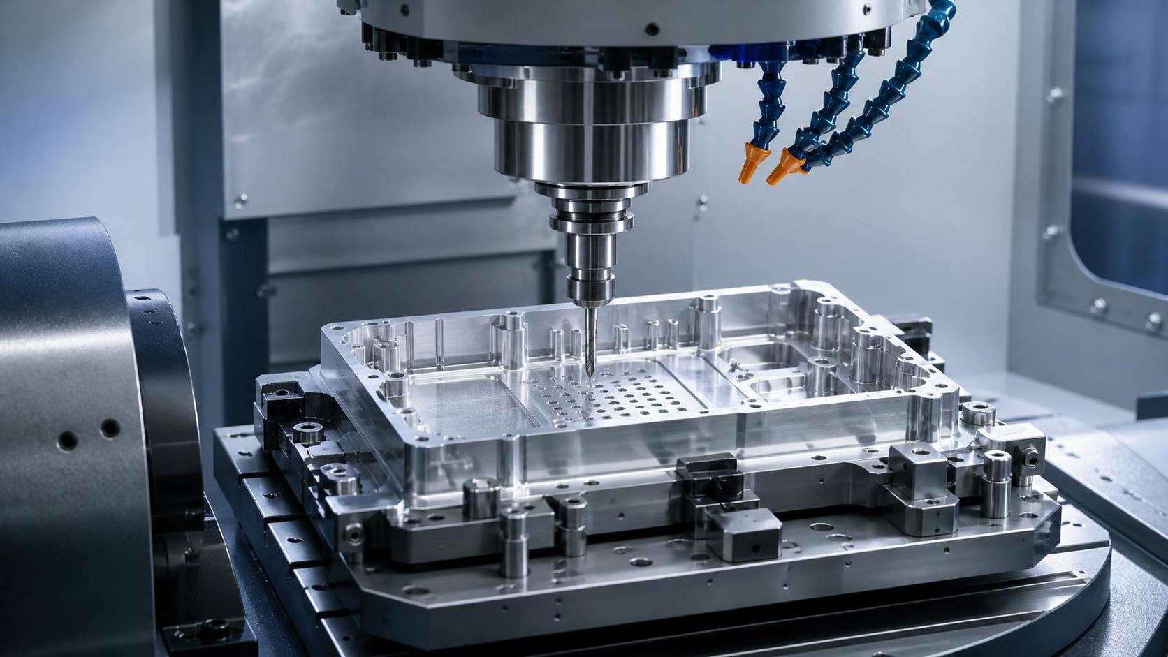
Start with the tolerance chain, not the catalog headline. In electronics production, a machine tool for electronics manufacturing has to hold accuracy across small features, thin walls, and heat-sensitive materials without drifting during long runs. A quoted positioning value on a clean test piece says very little by itself. The useful question is whether the machine can maintain dimensional stability when spindle heat rises, when tools wear gradually, when the part is clamped with limited force, and when multiple operations must reference the same datum without manual correction.
That usually shifts the evaluation away from broad machine categories and toward process fit. A machine chosen for aluminum housings, ceramic carriers, copper heat spreaders, connector components, shielding parts, or fixture plates may share a similar footprint, yet the ideal structure, spindle range, axis dynamics, and workholding approach can differ sharply. Tight-tolerance electronics work often fails at the interfaces between these factors rather than in any single specification line.
Define the real tolerance condition before comparing machines
Many selection errors begin with an incomplete drawing review. A part may show a few narrow tolerances, but the production risk often sits elsewhere: flatness after material removal, coaxiality between drilled and milled features, burr limits on edge connectors, or surface condition where adhesives, coatings, or thermal interfaces will be applied. If the process includes secondary assembly, then feature-to-feature consistency can matter more than absolute size on a single dimension.
Before comparing machine tools, separate the requirement into three layers. First, identify the dimensions that directly affect electrical fit, thermal contact, shielding performance, or assembly alignment. Second, note the features most sensitive to deflection, such as deep pockets in aluminum, small drilled patterns in stainless steel, or slots close to unsupported edges. Third, map how those features are created in sequence. A machine may be precise enough for each cut individually and still create stack-up error if the setup has to be broken, re-clamped, or transferred.
At this stage, it is also worth deciding whether the target condition must be held in one operation, in one setup, or only after a controlled finishing pass. Those are different machine requirements. A single-setup process may favor a multi-axis platform with strong probing and datum recovery. A finishing-pass strategy may place more weight on thermal stability and predictable axis behavior late in the cycle.
Match machine structure to part size, material, and feature density
Electronics components often look small and simple, which can lead to overestimating what a light machine can do. Small parts do not automatically mean low process load. Copper alloys can generate significant cutting resistance and heat. Thin covers and chassis parts can distort under clamping. Graphite, certain ceramics, and filled engineering materials raise issues around dust control, spindle sealing, and contamination of guideways.
A rigid casting and stable axis layout matter even when removal volumes are modest. For compact high-precision work, short force paths and good damping usually contribute more than travel range beyond the actual envelope. If most parts fit within a limited working area, extra travel may only increase thermal variation and motion time. Machines designed around compact precision zones often perform better on fine-feature repetition than larger general-purpose platforms.
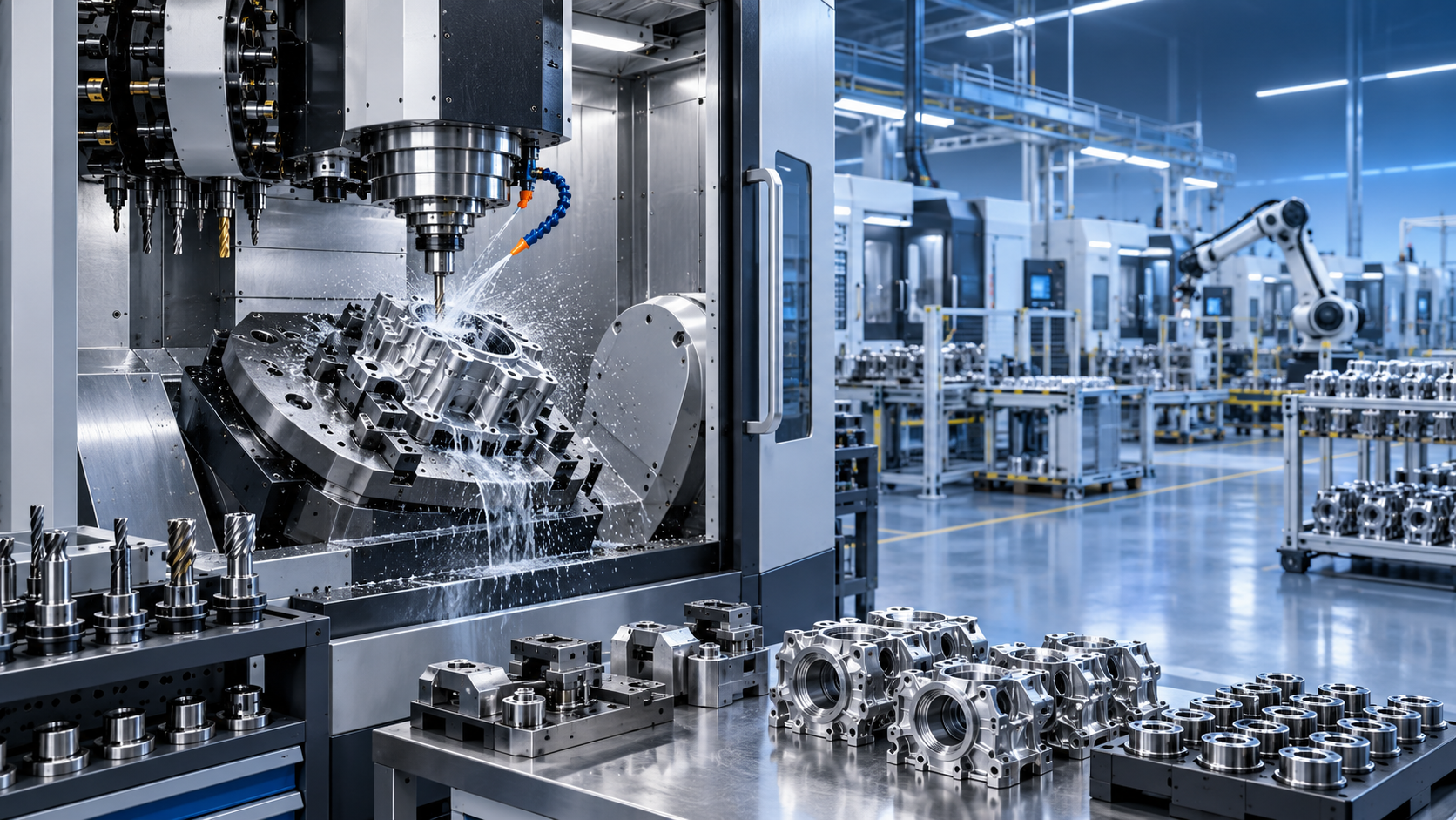
Look closely at how the machine handles the material family that dominates the job mix. For aluminum and magnesium alloys used in housings or frames, rapid evacuation of chips and stable high-speed finishing are central. For stainless or nickel-bearing alloys used in special shielding or structural inserts, spindle torque at low to mid ranges and axis stiffness under interrupted cutting become more important. If brittle materials are involved, vibration behavior, runout control, and coolant strategy can be more decisive than raw horsepower.
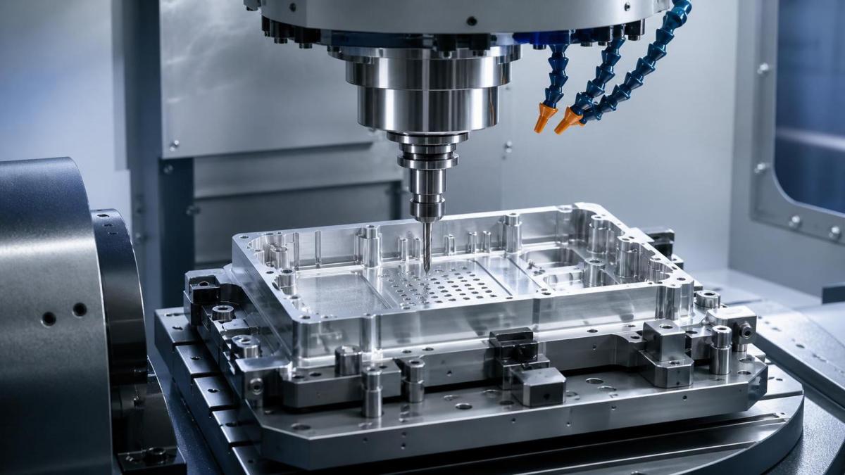
Spindle selection should follow the feature set, not maximum speed alone
High spindle speed attracts attention in electronics machining because many parts use small tools, but maximum rpm is only one part of the picture. The spindle must also control runout, thermal growth, bearing condition, and acceleration between tool changes. A machine with very high nominal speed may still perform poorly if it cannot hold stable surface finish on tiny end mills or micro drills over repeated cycles.
Evaluate spindle behavior around the speeds actually used for the process. If most operations are light finishing with tools below a few millimeters, acceleration time, balance quality, and vibration at working rpm deserve close attention. If the route includes roughing in aluminum blocks before finishing thin details, then broad usable power and stiffness across a mixed range matter more than a headline top speed.
Tool interface choice also has direct implications. For precision electronics parts, a holder system with strong concentricity control and repeatable length setting reduces cumulative variation, especially where small cutters are involved. If thermal shrink, hydraulic, or high-precision collet systems are under consideration, the selection should reflect the actual mix of tool diameters, change frequency, and presetting discipline rather than theoretical precision alone.
Thermal behavior often separates acceptable machines from dependable ones
When tolerances tighten, thermal management becomes a machine selection issue rather than a maintenance topic. Electronics parts are frequently small enough that a few microns of spindle or ballscrew growth can shift a critical fit. The problem becomes more visible in long unattended runs, mixed cycles with different spindle loads, or day-to-night ambient changes.
Ask how the machine manages heat at the spindle, motor drives, and axis system. Cooling arrangements, warm-up routines, compensation logic, and enclosure airflow all influence the result. Compensation features can be useful, but they should not be treated as a substitute for stable mechanical behavior. If the machine depends heavily on software correction while the base structure moves significantly with temperature, process validation becomes harder and drift after service events may be more difficult to predict.
The installation environment belongs in the same conversation. A high-precision machine placed near open loading doors, furnace traffic, wash stations, or strong afternoon sunlight may never deliver the same result it showed during acceptance testing. Floor condition, vibration from nearby equipment, and coolant temperature control can matter enough to change the recommended machine class.
Axis accuracy is only useful when repeatability survives production handling
Linear scale feedback, fine interpolation, and favorable pitch-error compensation sound attractive, but production reality adds pallet swaps, tool changes, door cycles, probe contact, and chip contamination. For electronics manufacturing, the machine should recover reference conditions quickly and consistently after these interruptions. That is especially true for parts with dense hole patterns, cavity arrays, or mating features spread over a broad face.
Backlash, reversal behavior, contouring quality on short moves, and servo tuning under frequent micro-positioning deserve attention. A machine can perform well on large circular test paths and still hesitate on tiny linked moves around narrow slots or connector reliefs. If the application includes miniature features or repeated peck cycles, observe actual motion quality during a representative cut rather than relying on generic interpolation claims.
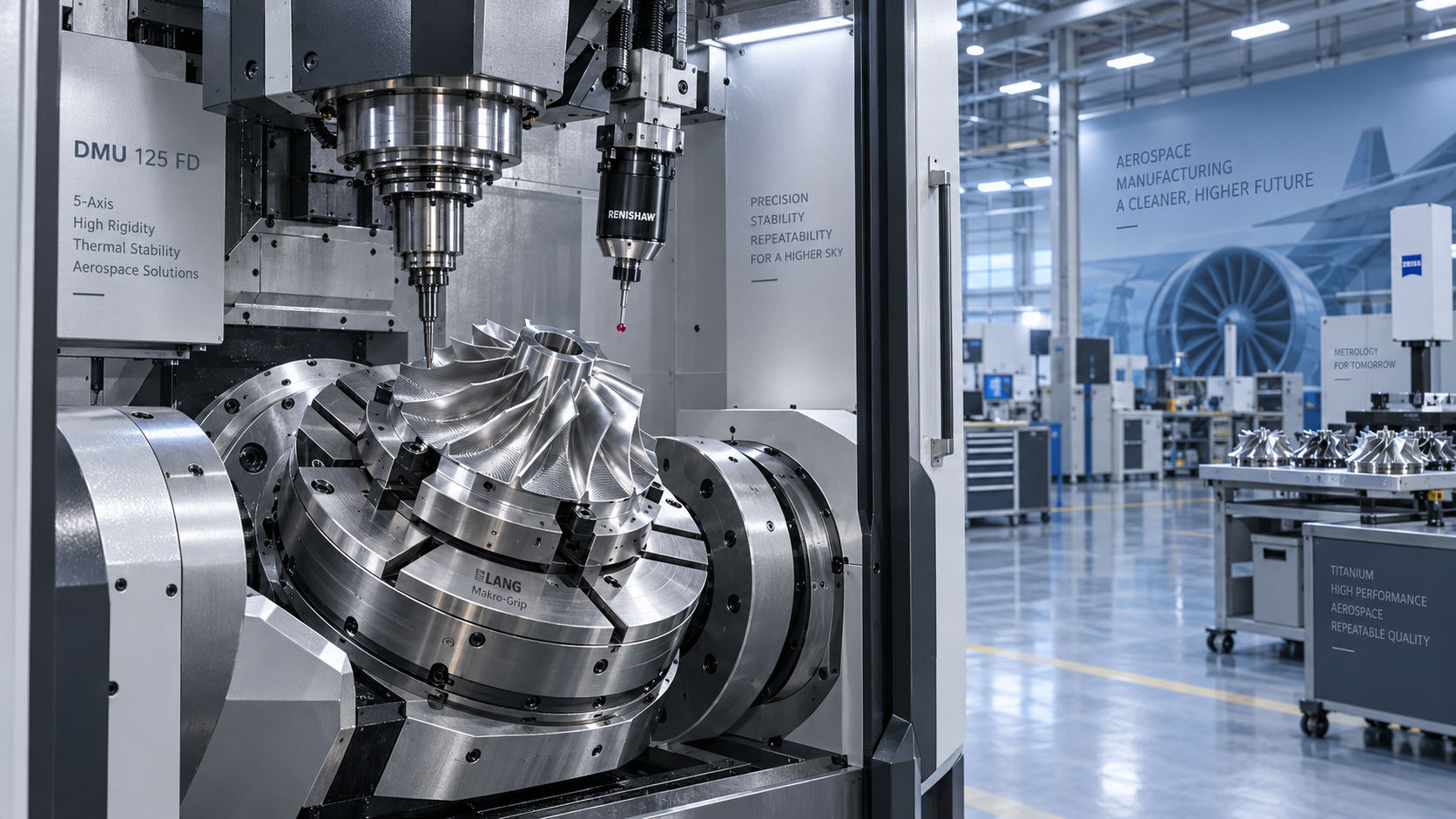
Probing capability should be considered part of the machine system, not an optional accessory. In tight-tolerance work, in-process probing can recover datum shifts, verify stock condition, and support tool breakage detection before an entire batch drifts out of tolerance. What matters is not just whether a probe can be installed, but how naturally it fits the control workflow and whether cycle interruptions remain manageable.
Workholding and fixturing can erase the gains of a good machine
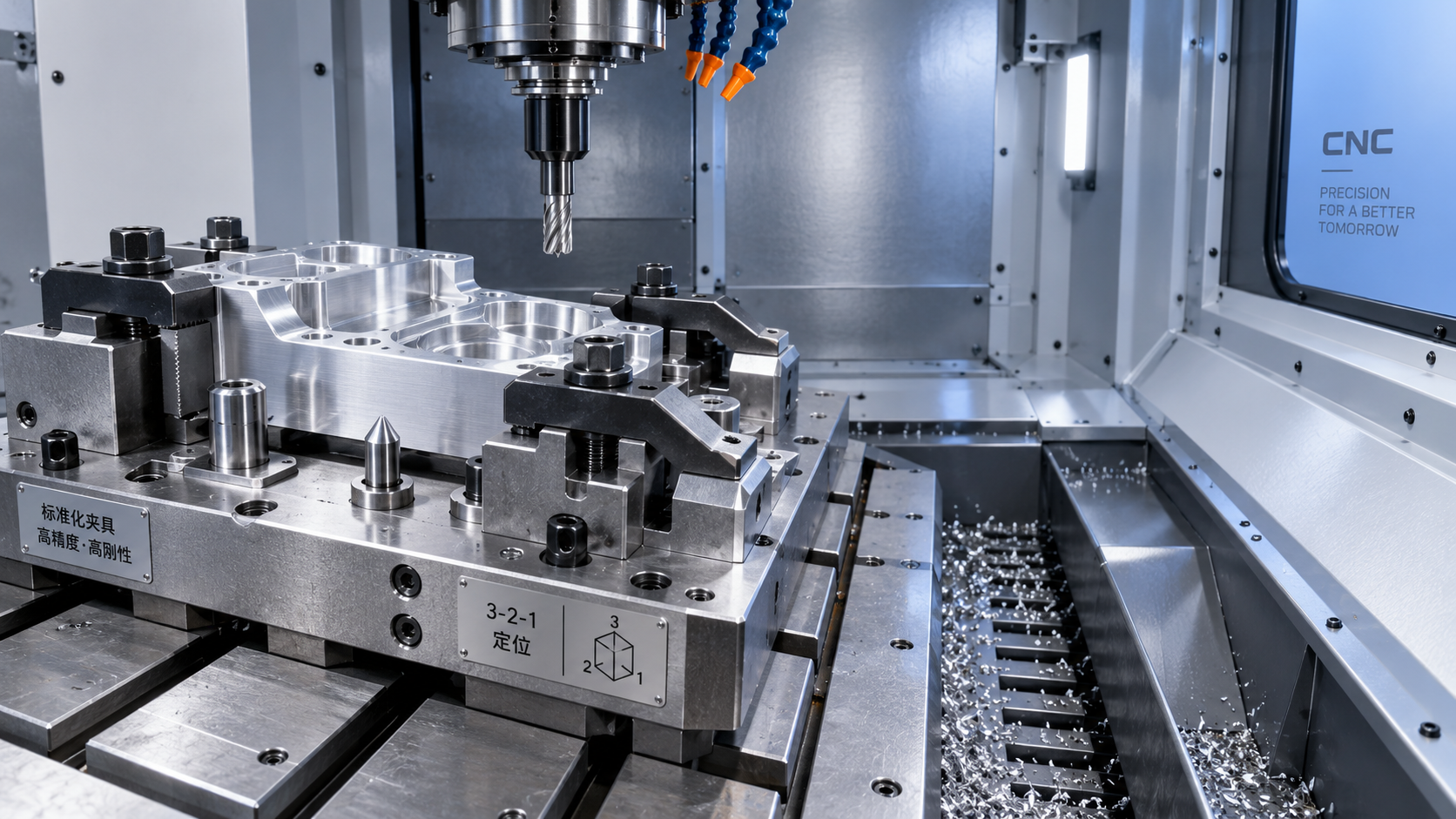
Electronics components often have cosmetic surfaces, thin sections, or areas reserved for thermal pads, conductive coatings, or sealing features. Excessive clamping can deform the part; weak clamping can allow chatter or feature shift. The machine selection should therefore account for the fixture concept from the beginning. Table size, access for low-profile clamps, vacuum fixture compatibility, pneumatic routing, and the ease of integrating modular nests all influence final precision.
If the expected production mix includes families of similar parts, fast fixture changeover may outweigh a small difference in theoretical axis accuracy. A slower but highly repeatable setup method can produce better overall conformity than a faster machine requiring frequent manual touch-off. In some lines, the better choice is a machine that supports stable referencing and easy fixture validation, even if its raw rapid traverse is not the highest.
Automation compatibility should be judged by recovery behavior
For unattended or lightly attended production, the machine must do more than accept a robot or pallet handler. It needs predictable restart logic after alarms, secure management of tool life offsets, reliable chip evacuation, and clear status signals that upstream systems can read without ambiguity. Electronics parts may produce fine chips, stringy burrs, or dust depending on the material, and these byproducts can interrupt automated handling long before the machine reaches a mechanical limit.
Tool magazine design also matters here. Dense part programs with many small drills, chamfer tools, and specialty cutters can push magazine organization, tool identification, and spare pocket planning harder than larger-part machining would suggest. If sister tools are needed to protect unattended runs, the control and magazine capacity should support that strategy cleanly.
Look past the purchase specification into service and validation effort
A machine that appears technically suitable can still be expensive to put into stable use if commissioning requires extensive parameter tuning, fixture redesign, or repeated postprocessor adjustment. Review what is needed to qualify the machine for the intended process: sample cutting under realistic material condition, measurement method alignment, training on thermal warm-up practice, spare parts lead assumptions, and preventive maintenance windows.
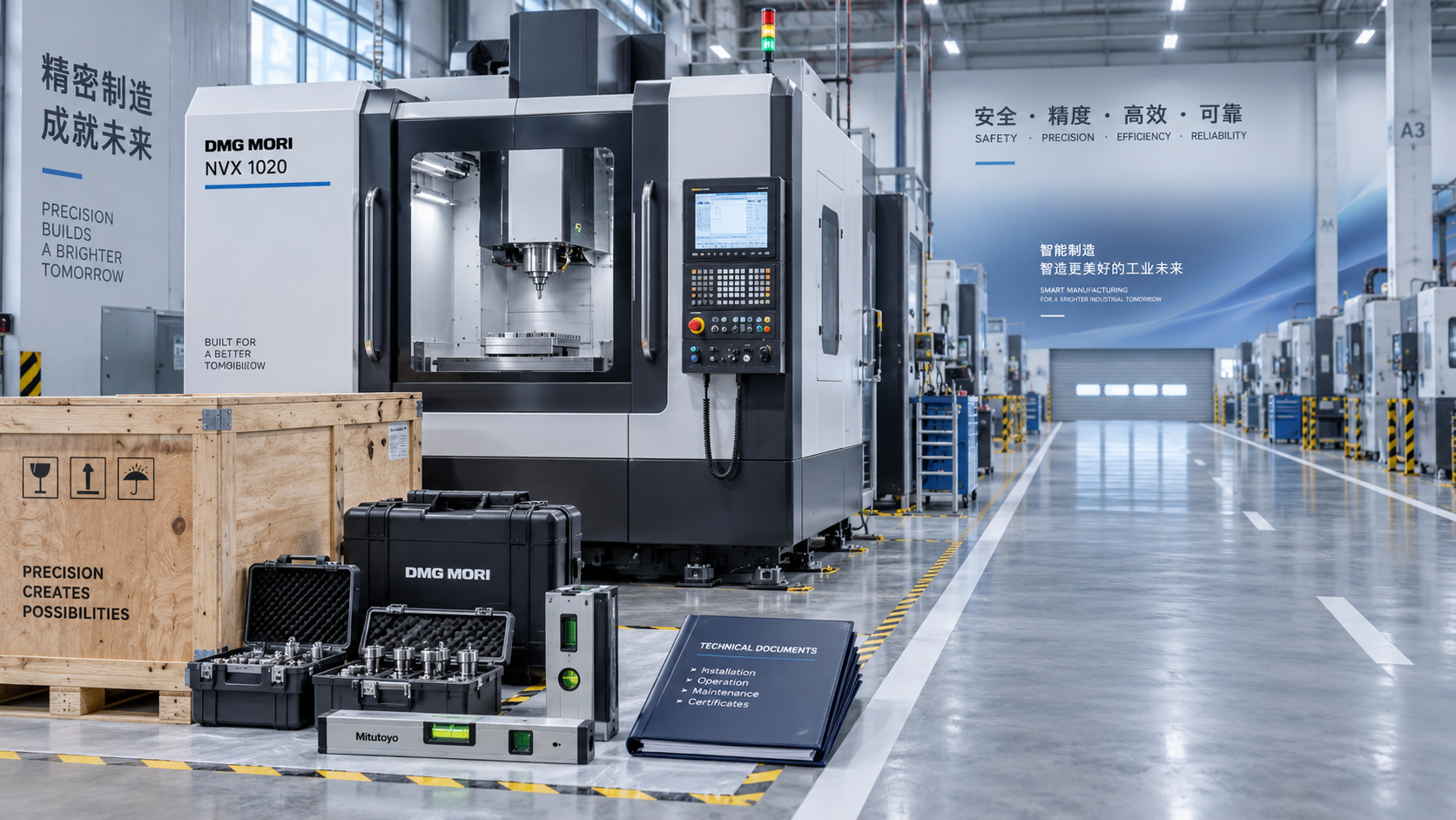
Transport and installation should not be treated as routine logistics. Precision machines can lose performance if they are moved without proper leveling checks, spindle handling precautions, or controlled startup procedures after relocation. If the machine will be installed in a building with vibration concerns, restricted rigging paths, or constrained coolant and air infrastructure, those conditions should be resolved before final selection.
It is also useful to ask how the machine behaves after maintenance events. Some platforms return to process quickly after spindle replacement, scale service, or axis adjustment; others need a deeper requalification effort. For electronics production where small deviations can affect assembly yield, that distinction can be more important than a marginal difference in advertised accuracy.
Common evaluation mistakes
- Comparing machines on a generic test coupon instead of a representative part or feature cluster. The resulting choice may favor headline precision while hiding burr, vibration, or clamping problems.
- Assuming that a faster spindle automatically improves small-feature quality. Without stable holders, thermal control, and low runout, higher speed may shorten tool life or worsen finish.
- Ignoring chip and dust behavior. Fine conductive chips, abrasive particles, and packed pockets can disrupt probing, contaminate fixtures, and create intermittent dimensional faults.
- Treating automation readiness as an interface question only. In practice, error recovery, tool management, and unattended cleanliness often determine whether the cell stays productive.
- Overvaluing travel range. For many electronics applications, compact rigidity and thermal consistency produce better results than unused machine envelope.
A sound selection usually emerges when the machine is judged as part of a working process: material condition, tooling, fixture behavior, control strategy, thermal environment, and maintenance discipline. If any of those elements remain undefined, the machine comparison will tend to drift toward marketing numbers that are easy to quote and hard to convert into stable production.
Recommended for You
 Industrial Machining: Selecting Processes for Tight-Tolerance Metal PartsCNC Machining Technology Center
 Manufacturing Technology Trends That Improve Throughput and Quality ControlManufacturing Market Research Center
 How to Design Cost-Effective Fixtures That Maintain Cycle Time in Mass ProductionCNC Machining Technology Center
 Is Learning CNC Programming Worth It for Shop Owners Seeking Higher Margins?CNC Machining Technology Center
 CNC Machine Arrival Inspection: Check Shipping Damage, Accuracy, Safety, and DocumentsCNC Machining Technology Center
 How to Select a Machine Tool for Aerospace Parts with Tight Tolerances?Machine Tool Industry Editorial Team

Aris Katos
Future of Carbide Coatings
15+ years in precision manufacturing systems. Specialized in high-speed milling and aerospace grade alloy processing.
▶
Industrial Machining: Selecting Processes for Tight-Tolerance Metal PartsCNC Machining Technology Center▶
How Does Precision Machining Differ From Standard Machining?CNC Machining Technology Center▶
CNC Precision: Which Tolerances, Materials, and Processes Fit Your Part?CNC Machining Technology Center▶
How to Choose Metal Machining Processes for Tight Tolerances and Production VolumeCNC Machining Technology Center▶
Production Process Explained: Key Stages, Controls, and Quality CheckpointsCNC Machining Technology Center
Mastering 5-Axis Workholding Strategies
Join our technical panel on Nov 15th to learn about reducing vibrations in thin-wall components.

Providing you with integrated sanding solutions
Before-sales and after-sales services
Comprehensive technical support