• Global CNC market projected to reach $128B by 2028 • New EU trade regulations for precision tooling components • Aerospace deman
NYSE: CNC +1.2%LME: STEEL -0.4%

How Does a High Precision CNC Machine Tool Improve Tolerance Control in Aerospace Parts?
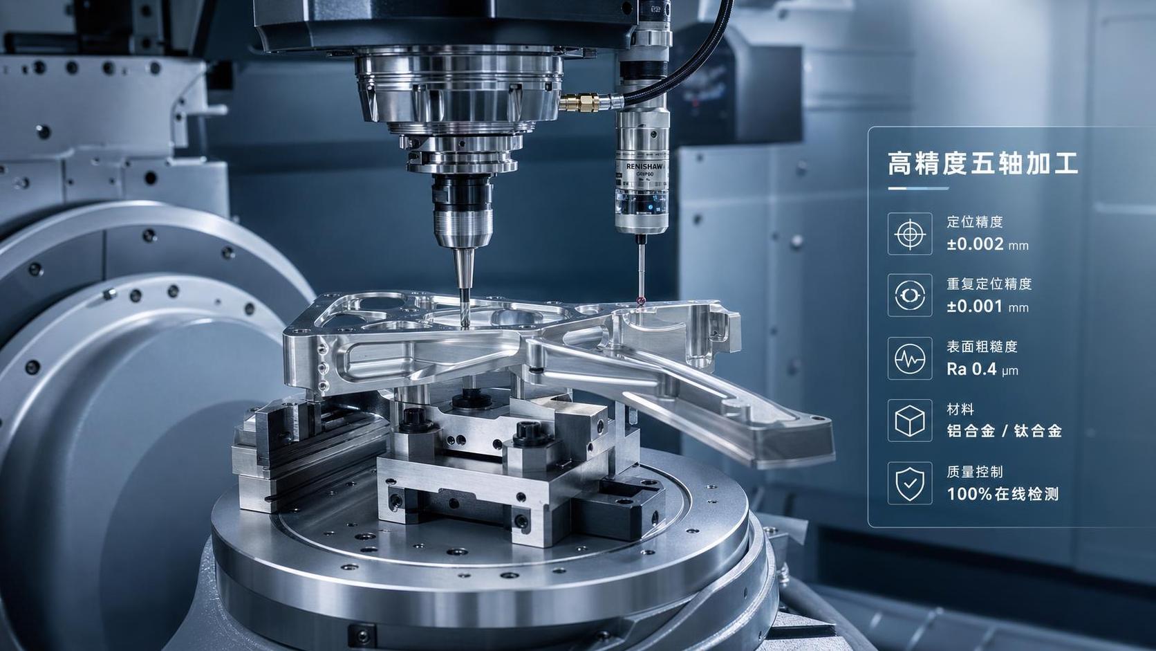
How Does a High Precision CNC Machine Tool Improve Tolerance Control in Aerospace Parts?
In aerospace manufacturing, even a micron-level deviation can affect part performance, safety, and compliance. A High Precision CNC Machine Tool plays a critical role in improving tolerance control by delivering stable accuracy, repeatable machining, and better process consistency for complex components. For technical evaluators, understanding how these machines reduce dimensional variation and support demanding aerospace standards is essential when assessing production capability and long-term manufacturing reliability.
If you are evaluating equipment for aerospace work, the question is usually not whether the machine can cut metal. Most modern CNC systems can. The real question is whether the machine can hold tolerance day after day, across part families, operators, ambient changes, tool wear, and long cycle times. That is where a high precision platform earns its place.
What follows is a practical checklist built around the issues that actually decide tolerance performance on aerospace parts: thin-wall housings, titanium brackets, structural aluminum components, engine-related precision features, and multi-face parts that must align after several setups. This is less about brochure claims and more about what to verify before trusting a machine on flight-critical or tightly regulated work.
Start with the tolerance requirement, not the machine spec sheet
A common evaluation mistake is to read positioning accuracy and repeatability figures in isolation. Those numbers matter, but they do not tell you enough unless they are tied to the actual feature tolerances on the part drawing.
For aerospace parts, the critical features are often not overall dimensions. More often, the hard requirements sit in true position, flatness, cylindricity, bore alignment, surface finish, and the relationship between machined datums. If a machine claims high precision but struggles to maintain geometric consistency after thermal growth or axis reversal, that gap will show up in inspection even when basic dimensions look acceptable.
- Check whether the machine’s achievable process capability has been demonstrated on features similar to yours, not just on a standard test coupon.
- Ask what portion of the drawing tolerance is being reserved for machine variation, and what portion is left for tooling, fixturing, material movement, and measurement uncertainty.
- If the supplier only shows nominal positioning data, that is incomplete for aerospace evaluation.
Look closely at thermal stability, because this is where good machines separate themselves
In real shops, thermal drift is one of the biggest sources of dimensional variation. Long spindle runs, coolant temperature changes, ball screw heating, and day-night ambient swings all move the machine structure. Aerospace parts with deep cavities, long bores, or extended cycle times feel that movement quickly.
A High Precision CNC Machine Tool improves tolerance control when its structure, spindle system, feedback loop, and compensation strategy are designed to manage heat rather than simply tolerate it. That can include temperature sensors, compensation logic, chilled coolant arrangements, stable casting design, and spindle warm-up routines. The exact method varies by builder, but the evaluation principle is straightforward: can the machine stay dimensionally stable from cold start to full production?
This is worth testing under realistic conditions. A machine that holds size on the first part but drifts by the fifth hour is not solving the problem.
Do not ignore structural rigidity and damping
Aerospace materials are not forgiving. Titanium and nickel-based alloys can push a machine into chatter or deflection if rigidity is marginal. Aluminum can be just as troublesome in a different way, especially on thin-wall parts where cutting forces release residual stress and the part moves during machining.
When a machine platform has better rigidity and vibration control, tolerance performance improves because the cut becomes more predictable. Tool life is steadier. Surface finish improves. Bore sizes stop wandering during rough-to-finish transitions. You also get a better chance of holding form tolerances without resorting to excessive spring passes.
Practical check: ask how the machine behaves during interrupted cuts, high aspect-ratio tool engagement, and long-reach finishing. Those situations expose weakness faster than any static spec.
Feedback system quality matters more than headline speed
For aerospace tolerances, servo response and feedback resolution matter because the machine must follow complex toolpaths without overshoot, lag, or contouring error. Five-axis machining makes this even more important. Poor synchronization between rotary and linear axes can show up as blend marks, profile deviation, or mismatch between adjacent surfaces.
You are not just buying travel speed. You are buying controlled motion under load.
- Ask whether linear scales are used on the critical axes if your application justifies them.
- Review backlash compensation strategy and axis calibration practice.
- For multi-axis parts, check how often volumetric accuracy is verified and whether the builder supports compensation for kinematic error.
If the application involves blade-like surfaces, impeller geometry, or compound-angle hole patterns, this part of the evaluation deserves extra weight.
Probe integration is not a luxury on tight aerospace work
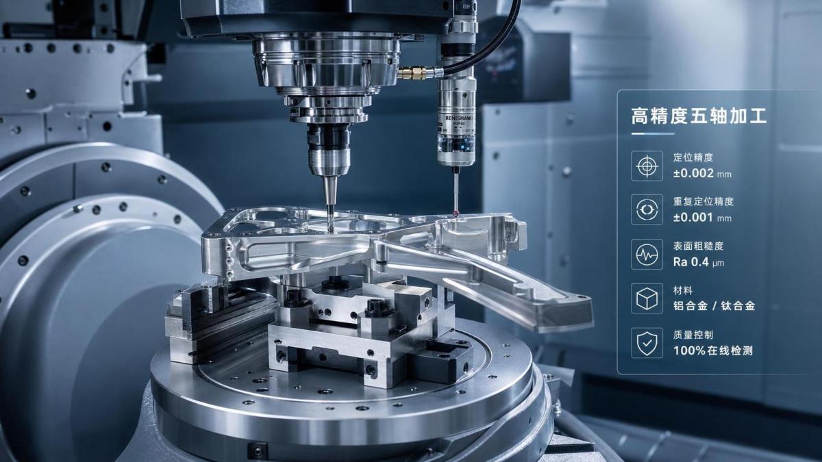
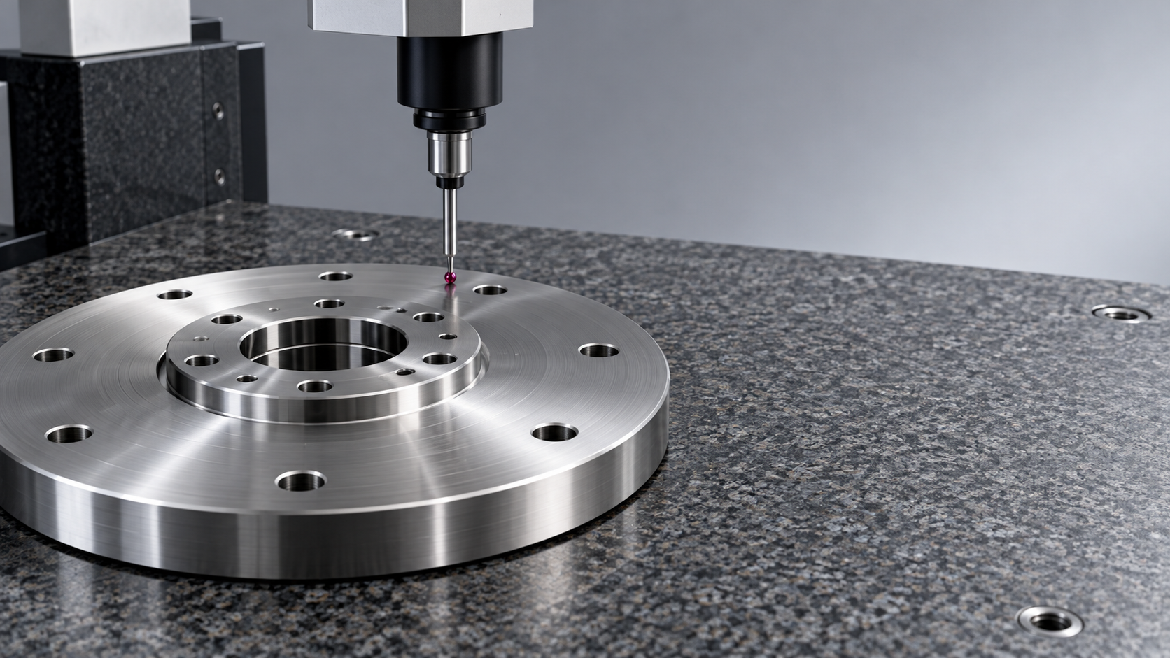
Machines improve tolerance control when they can measure, correct, and continue without waiting for a separate inspection loop on every issue. On-machine probing helps with work offset verification, in-process feature checks, broken tool detection, and compensation updates. It does not replace CMM validation where required, but it reduces the amount of variation that escapes downstream.
For technical evaluators, the key question is whether the probing system is integrated into the process or treated as an optional accessory nobody uses. There is a big difference.
In shops running complex aerospace parts, a stable process often depends on catching drift early: tool length shift, slight fixture contamination, stock variation, or part movement after roughing. Without in-cycle feedback, those problems tend to appear late, after the expensive machine time has already been spent.
Fixture strategy and machine precision have to match
This is an area where teams sometimes overestimate what a premium machine can fix. A high precision CNC platform cannot compensate for a fixture that distorts a thin wall, fails to locate repeatably, or leaves chips trapped on a datum surface.
For aerospace parts, especially lightweight structures, fixture force control is often part of tolerance control. So is datum strategy across setups. If a component is machined on multiple faces, you need confidence that the machine can repeat the spatial relationship between setups, but you also need fixturing that does not reintroduce error each time the part is loaded.
Process repeatability is the real test, not one perfect sample part
A lot of machines can produce a good demonstration part under managed conditions. Aerospace work asks a harder question: can the process repeat across a production batch, after tool changes, over multiple shifts, and after maintenance intervals?
When evaluating tolerance control, ask for evidence of repeatability over time. That may include in-house capability studies, inspection trend data, or controlled trial runs. Exact acceptance criteria depend on your quality system and customer requirements, so it is better to align them with your own drawing and process validation rules than to rely on generic claims.
If no repeatability evidence is available, treat the machine as unproven for your application. That is not a criticism. It is just a realistic purchasing posture.
Check the standards and quality framework around the machine
Aerospace tolerance control is not only a machine issue. It sits inside a quality system. Depending on the market and customer, technical evaluators may need to look at alignment with AS9100 quality management requirements, process validation practice, calibration control, traceability, first article inspection under AS9102 where applicable, and measurement system discipline. The machine contributes to capability, but the surrounding controls determine whether that capability can be trusted and documented.
On the metrology side, confirm how the shop verifies the machine itself. Laser calibration, ball bar testing, geometric accuracy checks, and periodic maintenance records all matter. The right verification method depends on machine type and application, and internal acceptance limits should be tied to product tolerance risk.
Be careful with vague statements like “aerospace grade” if they are not backed by documented process controls.
Material behavior should be part of your machine assessment
Tolerance performance on aerospace parts is heavily influenced by the material itself. Titanium work can amplify heat and tool wear issues. Aluminum structural parts may move after roughing because of residual stress. High-strength alloys can expose spindle load instability and tool deflection. A machine that appears accurate on one material may struggle on another.
So when someone says a High Precision CNC Machine Tool improves tolerance control, ask: on which material, with which cutter strategy, over what cycle time, and against which feature class? Without that context, the statement is too broad to be useful.
What to ask before approving a machine for aerospace tolerance work
- Has the machine been validated on parts with similar geometry, material, and tolerance risk?
- What thermal compensation or stabilization methods are built into the platform?
- How is volumetric or multi-axis accuracy checked and maintained?
- What in-process measurement functions are routinely used, not just installed?
- How does the supplier or factory demonstrate repeatability across a production run?
- What calibration, maintenance, and quality records are available for review?
- Are the machine’s strengths aligned with your actual bottleneck: fine bore stability, positional accuracy, thin-wall distortion control, or surface integrity?
That last question is easy to overlook. Some shops buy precision where they actually need rigidity, or they chase spindle speed when their bigger problem is thermal drift. Matching the machine to the failure mode is where good evaluation work pays off.
A practical way to judge the claim
A High Precision CNC Machine Tool improves tolerance control in aerospace parts when it reduces variation that would otherwise come from thermal movement, structural deflection, motion error, setup inconsistency, and weak process feedback. That improvement is real, but it should be verified in the context of your part family, your inspection method, and your quality requirements.
If you are evaluating a machine for aerospace use, do not stop at the catalog. Review how it behaves in a sustained process, how it is measured, and how it fits into the factory’s control plan. That is usually where tolerance confidence is either earned or exposed.
Recommended for You
![]() FANUC Links FIELD System Data with Copilot to Advance Shop-Floor Data UseCNC Machining Technology Center
FANUC Links FIELD System Data with Copilot to Advance Shop-Floor Data UseCNC Machining Technology Center Smart Manufacturing for Aerospace: Building Traceability Across CNC OperationsCNC Machining Technology Center
![]() Mitsubishi Electric Announces Physical AI System Linking Humanoid Robots and CNC MachinesMachine Tool Industry Editorial Team
Mitsubishi Electric Announces Physical AI System Linking Humanoid Robots and CNC MachinesMachine Tool Industry Editorial Team Precision Machining for Defense: Supplier Quality and Traceability ChecksManufacturing Market Research Center
![]() Nidec Machine Tool Launches MVR-5X Five-Axis Gantry MachineMachine Tool Industry Editorial Team
Nidec Machine Tool Launches MVR-5X Five-Axis Gantry MachineMachine Tool Industry Editorial Team Choosing a Precision Disc Parts Manufacturer in China: Tolerances and Quality ChecksManufacturing Market Research Center


Aris Katos
Future of Carbide Coatings
15+ years in precision manufacturing systems. Specialized in high-speed milling and aerospace grade alloy processing.
▶
How thermal drift affects accuracy in high-precision manufacturingCNC Machining Technology Center▶
Industrial Machining: Selecting Processes for Tight-Tolerance Metal PartsCNC Machining Technology Center▶
How Does Precision Machining Differ From Standard Machining?CNC Machining Technology Center▶
CNC Precision: Which Tolerances, Materials, and Processes Fit Your Part?CNC Machining Technology Center▶
How to Choose Metal Machining Processes for Tight Tolerances and Production VolumeCNC Machining Technology Center
▶
Mastering 5-Axis Workholding Strategies
Join our technical panel on Nov 15th to learn about reducing vibrations in thin-wall components.

Providing you with integrated sanding solutions
Before-sales and after-sales services
Comprehensive technical support