• Global CNC market projected to reach $128B by 2028 • New EU trade regulations for precision tooling components • Aerospace deman
NYSE: CNC +1.2%LME: STEEL -0.4%

Can a Mazak CNC retrofit retain the existing servo motors?
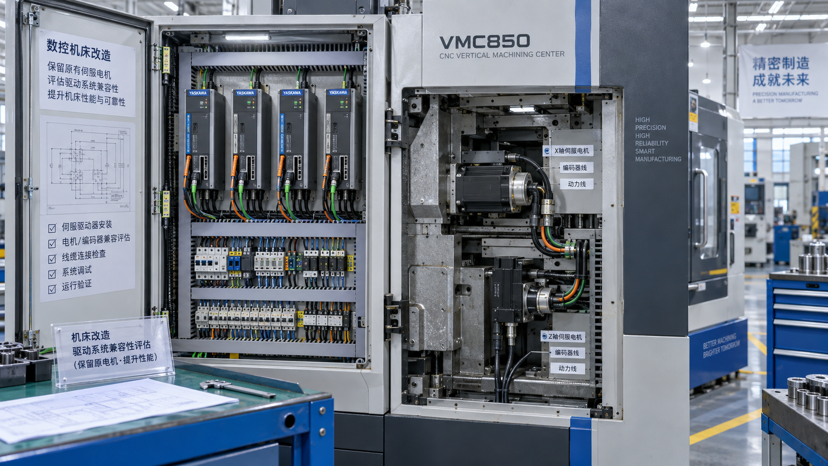
A Mazak CNC retrofit can retain the existing servo motors, but only when the proposed control-and-drive system supports their electrical characteristics, feedback devices, and operating requirements. A motor that still runs correctly on the original machine is not automatically compatible with a replacement drive. Equally, replacing the CNC does not necessarily require replacing the motors if the original drives can accept commands from the new control.
The decisive question is therefore not simply “Can the motors stay?” It is “Which parts of the existing motion-control chain can remain as a documented, supportable system?” The answer depends on the exact machine configuration, motor and amplifier models, feedback arrangement, and required machining performance—not the Mazak name alone.
Motor retention depends on the retrofit architecture
There are three practical approaches to evaluate. Each places the compatibility boundary in a different location.
Retaining both drives and motors avoids creating a new motor-to-drive pairing. However, it works only if the replacement CNC can communicate with those drives and obtain the feedback needed to close its control loops. A drive designed around an unsupported proprietary digital interface may prevent this approach even when the motor and amplifier are healthy.
Retaining motors while replacing drives moves the difficult interface downstream. The new drive must control the original motor correctly across acceleration, cutting loads, reversals, and thermal conditions. Similar power ratings or matching connector shapes are not evidence of compatibility.
Identify the installed hardware before selecting a control
Different Mazak models, production generations, and previous repairs can leave machines with different servo configurations. Begin with the machine’s electrical drawings and the actual component labels. Record the complete motor and amplifier part numbers, including suffixes, rather than relying on the machine model or control family.
The useful evidence package includes:
- Axis motor, servo amplifier, and feedback-device identification.
- Motor power, feedback, brake, and temperature-sensor wiring diagrams.
- Existing drive parameters and CNC axis settings, where retrievable.
- Supply arrangements, shared DC-bus connections, and regenerative hardware.
- Gear ratios, ballscrew pitch, travel limits, and reference-return arrangements.
- Any changes to motors, encoders, cables, or amplifiers made during earlier repairs.
Saved parameters can reveal current limits, feedback scaling, and tuning choices, but they are not necessarily complete motor specifications. A parameter backup also cannot establish that an unfamiliar replacement drive supports the motor. Missing documentation should be treated as an engineering task with a defined cost and resolution path, not as an assumption to be settled during commissioning.
Feedback compatibility is more than encoder resolution
An encoder can provide enough resolution for machining yet still be unusable with the proposed electronics. Compatibility includes the signal format, supply voltage, electrical interface, communication protocol, pinout, and the information required for motor commutation.
Incremental quadrature signals, resolver outputs, and serial absolute feedback are different interfaces. A drive that accepts one does not automatically accept another. Even within serial feedback systems, support must be confirmed for the specific device and implementation. An adapter cable changes connections; it does not translate an unsupported protocol.
For a permanent-magnet AC servo motor, the drive needs the rotor’s electrical position to apply current correctly. Depending on the design, that information may come from commutation tracks, an absolute encoder, a resolver, or a supported initialization procedure. Position pulses alone may not provide everything the drive requires. Incorrect commutation can cause unstable motion, excessive current, or failure to produce useful torque.
Replacing the encoder can make motor reuse feasible, but it is not a trivial accessory change. Mechanical fit, alignment to the rotor, electrical-angle calibration, environmental protection, and cable routing must all be resolved. The conversion also creates a modified motor assembly whose configuration needs to be documented for future maintenance.
Absolute position retention deserves separate attention. A replacement CNC may not interpret the original absolute-position data even if the drive still uses it internally. The machine may need a revised reference-return procedure, suitable switches, and confirmation that software travel limits become valid at the correct point in startup.
The command interface determines whether original drives can stay
When retaining the original amplifiers, identify what command they actually accept. Depending on the installed equipment, this may be an analog velocity or torque command, pulse-based positioning commands, or a digital communication interface. These arrangements place control responsibilities in different devices.
For example, an analog velocity-command arrangement can leave the velocity loop inside the drive while the CNC closes the position loop using accessible feedback. A torque-command arrangement places different demands on the controller’s loop execution and tuning. A position-command drive may close both loops locally. The proposed CNC must support the actual arrangement, not merely have an output with a similar name.
Axis enable, ready, fault, reset, and brake-related signals also need a defined handshake. A drive fault must lead to an appropriate machine response; it cannot be reduced to a warning on the new display while motion commands remain active.
Interface converters are acceptable only where their behavior is understood and supported. Update timing, latency, synchronization, fault propagation, and recovery behavior matter for coordinated machining. An interface that moves one axis successfully at low speed has not demonstrated reliable multi-axis contouring.
A new drive needs more than a matching kilowatt rating
If the original drives are being removed, establish whether the proposed replacements support the motor type and available motor data. Where applicable, this includes continuous and peak current, voltage requirements, torque and back-EMF constants, winding resistance and inductance, pole count, maximum speed, and thermal limits.
The drive must supply the required current without exceeding the motor’s permitted loading. Its voltage capability must also suit the intended speed range. A motor may operate correctly at low speed yet run out of voltage headroom during rapid traverse because of back EMF. Increasing current does not solve that limitation.
Permanent-magnet AC servos, brushed DC servos, and other motor types require appropriate drive technologies. A generic claim that a drive supports “older servos” is insufficient. An exact motor listing in the manufacturer’s supported configuration is strong evidence; where custom motor setup is permitted, the required characterization and commissioning procedure should be explicitly defined.
Temperature sensors and holding brakes need separate checks. The new electronics must interpret the sensor correctly or provide an appropriate protection arrangement. Brake voltage, release timing, and power supply requirements must be maintained. On a vertical axis, brake sequencing and controlled stopping require particular care: a holding brake should not be assumed suitable for repeatedly stopping a moving load.
Serviceable motors still need condition assessment
Electrical compatibility answers whether a motor can work with the new system. Condition assessment answers whether retaining it is sensible. Bearing wear, damaged feedback hardware, coolant ingress, deteriorated cables, and brake defects can undermine an otherwise valid retrofit.
Assessment should distinguish faults in the motor from faults in the cable, amplifier, or mechanics. Useful checks include winding-resistance comparison, insulation assessment using procedures appropriate to the motor, feedback inspection, connector examination, and review of operating temperatures and available fault history. Insulation testing must not expose attached encoders or electronics to unsuitable test voltages.
A no-load rotation test cannot establish performance under axis load. The motor must support the required acceleration and cutting duty without excessive heating, vibration, or following error. Existing performance records, where available, provide a valuable baseline before the original control is removed.
Motor reuse also cannot correct ballscrew backlash, coupling movement, guideway wear, or lubrication problems. These should be separated from electrical faults during assessment. Otherwise, an integration team may spend commissioning time adjusting servo gains to compensate for a mechanical defect that tuning cannot remove.
Acceptance should demonstrate machining performance, not just motion
Retaining an original motor does not guarantee original positioning accuracy. The replacement system changes some combination of feedback handling, command timing, loop tuning, and compensation. Conversely, a correctly integrated retained motor can remain suitable if it meets the machine’s intended duty.
Acceptance criteria should be agreed before committing to the hardware. Relevant checks include positioning accuracy and repeatability over the working travel, reversal behavior, following error during acceleration, coordinated interpolation, thermal behavior, and recovery after faults or power interruption.
Contour tests should reflect the intended work. A machine used for coordinated finishing needs evidence of acceptable path behavior, not only successful point-to-point positioning. Test conditions, feed rates, warm-up state, and load should be recorded so that results are interpretable and repeatable.
Safety validation belongs alongside performance validation. Emergency stopping, limit functions, drive-fault response, and vertical-axis restraint must be reassessed where the retrofit changes their implementation. Retaining legacy drives does not automatically preserve the validity of the original safety arrangement, and a normal servo-disable input should not be mistaken for a safety-rated function.
Compare the installed cost and supportability of each option
The relevant saving is not the price of avoided motors alone. Compare complete installed alternatives, including engineering, feedback conversion, cables, mechanical adaptation, drive setup, commissioning, downtime, and spare-parts provision.
Motor retention is a strong candidate when the hardware is healthy, the exact interfaces are documented, and the proposed system has a supported integration route. Its value weakens when savings depend on undocumented protocols, uncertain encoder conversions, or drives that cannot be repaired or replaced within an acceptable outage.
A quotation should identify which components remain, the evidence supporting each compatibility claim, and who is responsible for resolving interface problems. It should also define deliverables such as final schematics, parameter backups, motor configuration data, and acceptance results. “Reuse existing servos where possible” leaves too much uncertainty for a fixed project scope.
The spindle and auxiliary axes should be assessed separately. Successful reuse of the feed-axis motors does not establish compatibility for spindle orientation, synchronized threading, rigid tapping, or turret functions. Those dependencies can still determine whether the overall control replacement is viable.
A defensible retention decision rests on a traceable chain: the installed motor is identified and healthy; its drive and feedback interfaces are supported; the revised system meets the required duty; and performance and safety are demonstrated after integration. If a link in that chain remains unresolved, replacement should be priced as a defined alternative before the machine is dismantled—not treated as an unexpected commissioning expense.
Recommended for You
![]() Mitsubishi Electric Announces Physical AI System Linking Humanoid Robots and CNC MachinesMachine Tool Industry Editorial Team
 Precision Machining for Defense: Supplier Quality and Traceability ChecksManufacturing Market Research Center
![]() Nidec Machine Tool Launches MVR-5X Five-Axis Gantry MachineMachine Tool Industry Editorial Team
 Choosing a Precision Disc Parts Manufacturer in China: Tolerances and Quality ChecksManufacturing Market Research Center
![]() Siemens Executive Says AI Could Raise Factory Automation to 80%Manufacturing Market Research Center
 Choosing Automated Machine Tools for High-Mix, Low-Volume ProductionMachine Tool Industry Editorial Team


Aris Katos
Future of Carbide Coatings
15+ years in precision manufacturing systems. Specialized in high-speed milling and aerospace grade alloy processing.
▶
Choosing a CNC Machine for Mold Making: Accuracy, Rigidity, and Surface FinishCNC Machining Technology Center▶
How to Cut CNC Machining Energy Use per Part Without Longer Cycle TimesCNC Machining Technology Center▶
Will a Mazak CNC retrofit work with your existing servo drives?CNC Machining Technology Center▶
Do energy-efficient machine tools reduce power use at partial load?CNC Machining Technology Center▶
Comparing energy-efficient machine tools by energy use per partCNC Machining Technology Center
▶
Mastering 5-Axis Workholding Strategies
Join our technical panel on Nov 15th to learn about reducing vibrations in thin-wall components.

Providing you with integrated sanding solutions
Before-sales and after-sales services
Comprehensive technical support