• Global CNC market projected to reach $128B by 2028 • New EU trade regulations for precision tooling components • Aerospace deman
NYSE: CNC +1.2%LME: STEEL -0.4%

What Is a Machining Process? Key Steps, Tools, and Tolerance Factors
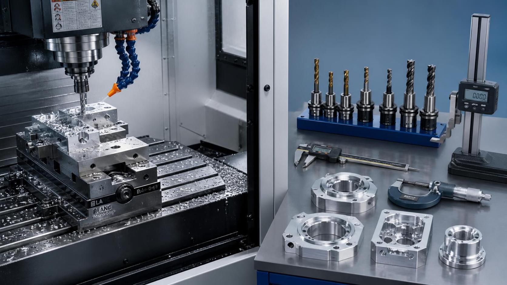
What Is a Machining Process?
A machining process is a controlled method of removing material from a workpiece to create a part with a required shape, size, surface condition, and functional fit. The starting material may be bar stock, plate, a forging, a casting, or an additively produced near-net-shape blank. Material is removed by cutting tools, abrasive media, or other controlled methods until the remaining geometry matches the engineering definition.
In practical manufacturing, machining is not simply “cutting metal.” It is a chain of decisions involving material behavior, machine capability, workholding, cutting data, tool access, inspection, and production volume. A shaft may need concentric journals and threads; a valve body may require intersecting internal passages; an aerospace structural component may demand thin walls without distortion. Each requirement affects how the part is made.
Modern CNC equipment makes this process repeatable by translating a programmed toolpath into machine movement. CNC lathes, vertical and horizontal machining centers, and multi-axis systems are now central to automotive, aerospace, energy equipment, electronics, and general industrial production. Yet automation does not remove the need for engineering judgment. It makes planning errors repeat faster, which is why process discipline remains as important as machine sophistication.
Machining Compared With Other Manufacturing Methods
Machining is often selected when dimensional control, surface finish, functional interfaces, or complex local features matter more than producing the basic material shape at the lowest possible cost. Casting, forging, stamping, molding, and additive manufacturing can all create useful starting forms, but they may not achieve the final accuracy needed for bearing seats, sealing faces, threaded holes, precision bores, or mating features.
That does not mean machining should be used for every feature. Removing a large volume of material from a solid block can be inefficient when a casting or forging could provide a closer starting shape. Conversely, a highly complex part may be easier to machine from billet in low volumes than to support with dedicated forming tooling. The sensible choice depends on geometry, material, annual demand, quality requirements, and the cost of downstream risk.
Many production routes are therefore hybrid. A forged transmission component may be turned, milled, drilled, heat treated, and finish-ground. A cast pump housing may be machined only on its critical mounting faces, bores, and sealing surfaces. The machining process is frequently the stage that converts a near-net shape into a functional assembly component.
The Core Steps From Drawing to Finished Part
A reliable route begins long before the first tool touches the material. Engineers review the drawing or 3D model to identify critical dimensions, datum references, tolerances, thread specifications, surface requirements, and inspection points. This review also exposes practical questions: Can a cutter reach the feature? Can the workpiece be clamped without covering a required surface? Is a deep bore truly necessary, or could the design be changed for easier manufacture?
The next step is material preparation. Stock is cut to length, castings are cleaned, or forgings are checked for sufficient machining allowance. Initial material condition matters. A part made from a material with residual stress, uneven hardness, or an inconsistent casting skin can behave differently as material is removed. For some components, rough machining is deliberately separated from final machining so the workpiece can stabilize before critical surfaces are completed.
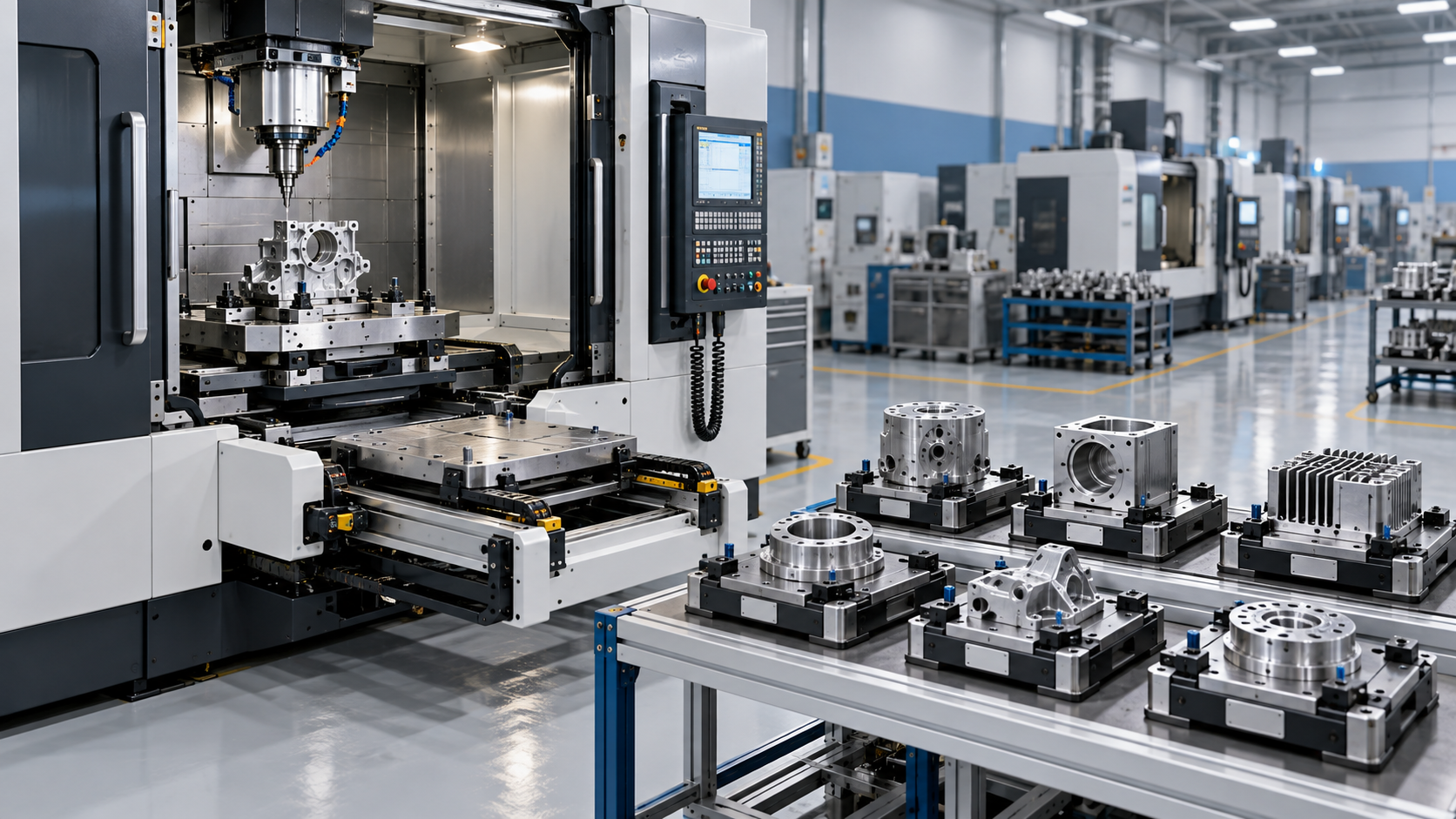
Setup planning follows. The machine, fixture, vise, chuck, collet, jaws, locating pins, or dedicated pallet fixture must hold the workpiece securely while maintaining clear tool access. The setup establishes the reference system used by the program. Poor datum strategy is a common source of accumulated error: each individual feature may appear acceptable, while its relationship to another feature is wrong.
Roughing removes most excess material quickly. The goal is controlled productivity, not final appearance. Semi-finishing may then leave a more consistent allowance before finishing tools establish the final dimensions and surface texture. Drilling, boring, reaming, tapping, thread milling, engraving, deburring, and edge breaking are added as the part design requires. Some parts return to the machine after heat treatment, coating, or another external process for final sizing.
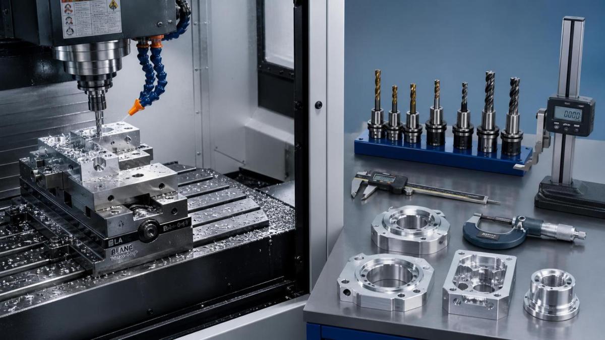
Inspection is not merely the final gate. In-process checks can detect tool wear, fixture movement, thermal drift, or programming errors before an entire batch is affected. Depending on the component, verification may use calipers and micrometers, bore gauges, height gauges, thread gauges, surface measurement equipment, or a coordinate measuring machine. The appropriate method depends on the feature and the tolerance being confirmed.
Common Machine Types and What They Are Best At
The machine architecture should follow the part rather than habit. CNC turning is the natural choice for rotational work such as shafts, bushings, flanges, rings, and threaded components. A turning center can face, turn diameters, cut grooves, drill axial holes, and, when equipped with driven tools, perform selected milling operations without moving the part to another machine.
Machining centers are generally used for prismatic parts and multi-face components. Vertical machines are common for plates, housings, brackets, and fixtures, while horizontal configurations can be advantageous when several sides must be machined and chip evacuation is difficult. Five-axis machining is valuable when features lie on angled surfaces or when a part benefits from being completed in fewer setups. It can reduce re-clamping, but it also raises demands on programming, collision control, fixture design, and machine calibration.
Grinding, electrical discharge machining, honing, and other specialist processes may be required where conventional cutting is not the best answer. Hardened material, very fine finishing requirements, intricate internal corners, or delicate forms can justify an additional process. The key question is not which method sounds most advanced; it is which route can consistently produce the specified feature with acceptable risk and cost.
Tools, Fixtures, and the Often-Underestimated Role of Workholding
Cutting tools determine how efficiently material can be removed. Typical tool families include carbide inserts for turning, end mills for milling, drills, reamers, taps, thread mills, boring bars, and form tools. Tool geometry, coating, rigidity, chip evacuation, coolant delivery, and programmed cutting conditions must suit the workpiece material. A tool that performs well in aluminum may be unsuitable for stainless steel or heat-resistant alloys.
Tool selection is also tied to feature design. Deep cavities may require long-reach cutters, but extending a tool reduces rigidity and can invite vibration. Small internal diameters may need slender boring bars that are more prone to deflection. Sharp internal corners can be problematic because rotating cutters have a radius; a design that allows a realistic corner radius is often easier to machine and inspect.
Fixtures deserve equal attention. The fixture must resist cutting forces without deforming the part, especially on thin-wall sections, soft materials, or unfinished cast surfaces. Excessive clamping force can distort a component during machining, only for it to spring back after release. Insufficient support can cause chatter, poor surface finish, or variation between parts. In higher-volume environments, well-designed fixtures and automated loading systems can improve repeatability as much as a faster spindle can.
How Tolerances Shape the Machining Strategy
Tolerance is the permitted variation from a nominal dimension or geometric requirement. It is often treated as a drawing detail, but it directly determines process complexity. A broad dimensional tolerance may allow a straightforward milling or turning operation. A tighter bore, flatness requirement, positional relationship, or runout limit may require more controlled setups, specialized tooling, additional finishing, and more frequent inspection.
The functional purpose of a feature should guide the tolerance. A clearance hole usually does not need the same control as a bearing fit. A decorative external surface may not need the finish required for a seal contact face. Applying tight tolerances indiscriminately can increase cost and lead time without improving how the assembly works. On the other hand, relaxing a tolerance without understanding its function can create leakage, vibration, assembly interference, or shortened component life.
Geometric tolerancing adds another layer. Diameter alone does not ensure that a hole is positioned correctly, that a shaft rotates without wobble, or that two faces sit parallel in assembly. Datums establish the references from which these relationships are controlled. When a drawing uses geometric tolerancing, the manufacturing plan and inspection plan need to use the same functional logic rather than checking unrelated dimensions in isolation.
Temperature is a less visible tolerance factor. Machines, tools, parts, and gauges expand or contract as conditions change. Heat is generated by spindle operation, cutting friction, coolant behavior, and the surrounding environment. Modern CNC systems may use compensation functions, probing, and monitoring, but thermal management still needs to be considered when requirements are demanding.
What Usually Causes Machining Variation?
Variation rarely has one simple cause. Tool wear gradually changes cutting behavior and can affect dimensions or surface condition. Vibration may leave visible chatter marks or subtly alter a bore. Chips trapped between a workpiece and fixture can shift the setup. Material inconsistency, incorrect offsets, coolant problems, spindle condition, and operator handling can all influence the result.
A stable process therefore relies on more than a capable machine. It needs documented setup practices, controlled tool life, clean locating surfaces, appropriate measuring methods, and feedback from inspection to production. In automated cells, these controls may be supported by probing, tool monitoring, pallet systems, robotic handling, and production data collection. Digital integration can make abnormalities easier to identify, but the data is useful only when teams know what action should follow.
Questions Worth Asking Before Releasing a Part for Machining
Before a component enters production, it is useful to confirm a few practical points:
- Which features are functionally critical, and which are cosmetic or non-critical?
- Are datum references clear enough for both machining and inspection?
- Can all required surfaces be reached without unstable, overly long tools?
- Does the material form—bar, plate, casting, forging, or another blank—leave suitable allowance?
- Will heat treatment, plating, coating, or assembly alter the final dimensions or surface condition?
- Is the expected volume better served by flexible CNC setups or dedicated workholding and automation?
These questions are especially relevant as factories move toward connected production lines. Industrial robots, flexible manufacturing systems, and smart-factory software can improve material flow and traceability, but they do not compensate for an unclear drawing or an impractical tolerance scheme. Automation works best when the underlying machining process is already stable.
Why Machining Knowledge Matters Across Global Manufacturing
Machine tool manufacturing has strong industrial bases in countries including China, Germany, Japan, and South Korea, while equipment suppliers, tool makers, automation specialists, and component producers operate across increasingly international supply networks. For buyers, engineers, and production planners, this broad ecosystem creates more options—but also makes technical communication more important. A complete RFQ or production package should clarify material grade, revision level, tolerances, surface requirements, inspection expectations, quantity, and any special handling needs.
The machining process is ultimately a controlled balance: remove material efficiently, preserve part stability, achieve the features that matter, and verify them in a way that reflects actual function. When evaluating a manufacturing route, start with the component’s critical interfaces rather than the machine name. That approach usually reveals whether the real constraint is geometry, material, workholding, tolerance, inspection, or production scale—and where further technical review is needed.
Recommended for You
![]() Mitsubishi Electric Announces Physical AI System Linking Humanoid Robots and CNC MachinesMachine Tool Industry Editorial Team
Mitsubishi Electric Announces Physical AI System Linking Humanoid Robots and CNC MachinesMachine Tool Industry Editorial Team Precision Machining for Defense: Supplier Quality and Traceability ChecksManufacturing Market Research Center
![]() Nidec Machine Tool Launches MVR-5X Five-Axis Gantry MachineMachine Tool Industry Editorial Team
Nidec Machine Tool Launches MVR-5X Five-Axis Gantry MachineMachine Tool Industry Editorial Team Choosing a Precision Disc Parts Manufacturer in China: Tolerances and Quality ChecksManufacturing Market Research Center
![]() Siemens Executive Says AI Could Raise Factory Automation to 80%Manufacturing Market Research Center
Siemens Executive Says AI Could Raise Factory Automation to 80%Manufacturing Market Research Center Choosing Automated Machine Tools for High-Mix, Low-Volume ProductionMachine Tool Industry Editorial Team


Aris Katos
Future of Carbide Coatings
15+ years in precision manufacturing systems. Specialized in high-speed milling and aerospace grade alloy processing.
▶
Choosing a CNC Machine for Mold Making: Accuracy, Rigidity, and Surface FinishCNC Machining Technology Center▶
How to Cut CNC Machining Energy Use per Part Without Longer Cycle TimesCNC Machining Technology Center▶
Will a Mazak CNC retrofit work with your existing servo drives?CNC Machining Technology Center▶
Do energy-efficient machine tools reduce power use at partial load?CNC Machining Technology Center▶
Comparing energy-efficient machine tools by energy use per partCNC Machining Technology Center
▶
Mastering 5-Axis Workholding Strategies
Join our technical panel on Nov 15th to learn about reducing vibrations in thin-wall components.

Providing you with integrated sanding solutions
Before-sales and after-sales services
Comprehensive technical support