• Global CNC market projected to reach $128B by 2028 • New EU trade regulations for precision tooling components • Aerospace deman
NYSE: CNC +1.2%LME: STEEL -0.4%

How to Evaluate CNC Manufacturing for Electronics: Tolerances, Materials, and ESD Risks
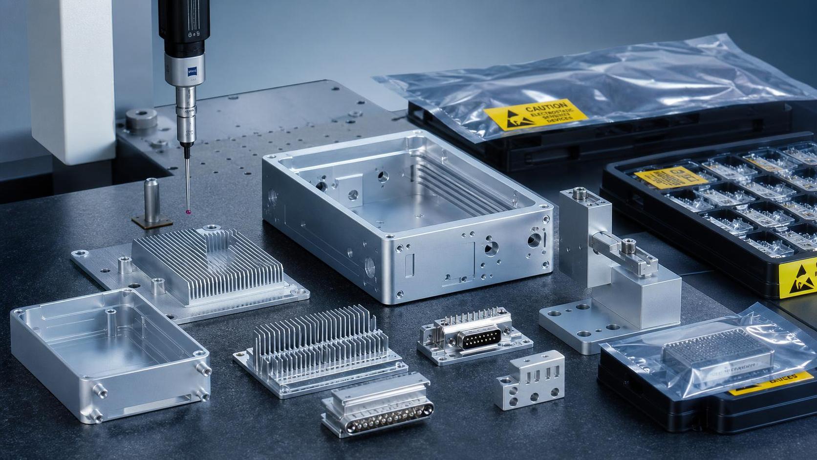
Evaluating CNC manufacturing for electronics starts well beyond spindle speed, hourly rate, or headline machine count. In electronic components and assemblies, small machining deviations can affect fit, shielding, grounding, thermal behavior, and long-term reliability.
That is why CNC manufacturing for electronics is receiving closer scrutiny across global production networks. As machine tool industries in China, Germany, Japan, and South Korea keep pushing precision, automation, and digital integration, the benchmark for machining suppliers has moved higher.
A capable supplier must show repeatable tolerances, material knowledge, clean surface control, and practical ESD discipline. For electronics work, those factors often matter more than a low quoted price.
Why Electronics Machining Needs a Different Evaluation Lens
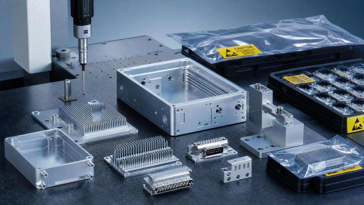
CNC manufacturing for electronics usually supports housings, heat sinks, fixtures, connector bodies, shielding parts, brackets, test interfaces, and precision structural elements. Many of these parts look simple, but their acceptance window is narrow.
In practical terms, the machined part often sits inside a larger chain. It may touch a PCB, support a sensor, protect signal integrity, or manage heat around sensitive devices.
A dimensional issue can create assembly stress. A poor finish can affect contact quality. Burrs can become contamination sources. Static discharge can damage components before final integration.
This is why CNC manufacturing for electronics should be assessed as a process capability question, not only a capacity question. The supplier needs to prove control, not just equipment ownership.
Tolerance Capability Is More Than a Drawing Number
Tolerance review is usually the first filter, but the important point is repeatability under production conditions. A supplier may machine one acceptable sample, yet still struggle during larger runs.
For CNC manufacturing for electronics, tolerance risk often appears in these areas:
- Flatness on mounting surfaces for PCB support or thermal interfaces
- Positional accuracy for connector openings, threads, and fastener patterns
- Wall thickness consistency in light enclosures and EMI shielding parts
- Datum control where multiple assemblies stack together
- Hole quality for press-fit inserts or precision alignment features
A useful evaluation asks how tolerances are achieved and verified. Machine type matters, but fixturing, tool wear control, probing routines, thermal compensation, and inspection planning matter just as much.
Multi-axis machining centers can reduce setups and improve positional consistency. Even so, process stability depends on whether the supplier controls the full machining route from raw stock to final inspection.
Questions behind the tolerance claim
The quoted tolerance should not be accepted in isolation. It is more useful to compare tolerance claims against part geometry, lot size, material, and finishing steps.
In electronics programs, dimensional capability should be reviewed together with final finish and assembly conditions. That gives a much more realistic view of production readiness.
Material Selection Affects Machinability and End Use Performance
Materials in CNC manufacturing for electronics are chosen for more than strength. Electrical behavior, thermal conductivity, weight, corrosion resistance, coating compatibility, and cleanliness all influence the decision.
Aluminum is common for enclosures and heat-management parts because it balances machinability, weight, and thermal performance. Stainless steel may be selected for durability or corrosion resistance, but it adds machining complexity.
Copper and copper alloys support thermal and electrical functions, yet burr control and deformation become more demanding. Engineering plastics can help with insulation or weight reduction, but dimensional stability must be checked carefully.
The right question is not simply which material is available. The question is whether the supplier understands how that material behaves during machining, cleaning, finishing, storage, and downstream assembly.
Typical material evaluation factors
- Lot traceability for regulated or reliability-sensitive applications
- Residual stress and distortion risk after roughing and finishing
- Compatibility with anodizing, nickel plating, passivation, or conductive coatings
- Cleanliness after machining fluids and chip removal
- Galvanic corrosion risk in mixed-material assemblies
For global supply chains, this matters even more. Different regions may offer similar material grades with different process discipline, certification depth, or finishing quality. Evaluation should therefore cover both specification and execution.
Surface Integrity Often Decides Functional Success
Surface integrity is often underestimated in CNC manufacturing for electronics. A part can pass dimensional inspection and still fail in use because the surface condition is wrong.
Surface roughness affects gasket sealing, thermal interface contact, coating adhesion, and cosmetic quality. Burrs can interfere with mating parts or create conductive debris in sensitive assemblies.
Edges are especially important. Sharp edges may damage cables, films, seals, or operator gloves. Overly aggressive edge breaks, however, can compromise fit or shielding performance.
Good evaluation therefore includes micro-level details: burr thresholds, scratch acceptance, edge condition, flatness after finishing, and residue limits after cleaning. These are not cosmetic extras in electronics work.
Where surface issues commonly appear
Typical risk zones include threaded holes, pocket corners, thin ribs, heat sink fins, connector cutouts, and surfaces that contact thermal pads or EMI gaskets. These features need targeted review during first article approval.
ESD Control Must Extend Beyond the Assembly Line
ESD risk is one of the clearest dividing lines between general machining and CNC manufacturing for electronics. Static damage may not be visible at shipment, yet it can shorten component life or cause intermittent failures later.
Machined parts themselves may not always be ESD-sensitive. The risk rises when parts are cleaned, handled, packed, or partially assembled near electronic devices, sensors, or boards.
A credible supplier should explain how ESD controls are applied in relevant zones. That includes grounded workstations, wrist straps where needed, conductive packaging, humidity awareness, and separation of ordinary and protected handling areas.
It also helps to verify whether cleaning cloths, trays, foams, and labels are suitable for ESD-sensitive workflows. Secondary handling materials are often where avoidable risk enters the process.
Practical signs of ESD readiness
- Defined ESD procedures linked to incoming, machining-adjacent, and packing stages
- Protected storage for parts destined for electronic assembly
- Routine verification of grounding and packaging materials
- Clear distinction between cosmetic handling and ESD-safe handling
When CNC manufacturing for electronics is outsourced internationally, ESD requirements should be written into quality documents, not left as verbal assumptions.
How to Compare Suppliers in a More Useful Way
A productive comparison framework combines machining capability, process control, and electronics-specific discipline. This gives a more realistic view than comparing quotations line by line.
Useful comparison areas include lead time stability, first article quality, inspection records, fixture design, finishing partners, cleanliness control, and packaging practice. Digital traceability is increasingly relevant as smart manufacturing expands.
Suppliers serving automotive, aerospace, energy equipment, and electronics often share advanced machine assets. What separates electronics readiness is how well they manage fine features, contamination, and handling sensitivity.
What to Review Before Moving Forward
Before approving CNC manufacturing for electronics, it helps to build a short decision file around the actual part family. That file should identify critical dimensions, material risks, finish expectations, cleanliness limits, and ESD-sensitive touchpoints.
Prototype results should be read carefully, especially where tolerance, finish, and post-processing interact. A part that looks acceptable in isolation may still create integration risk at system level.
The next step is usually not broad supplier expansion. It is tighter definition. Clarify inspection methods, request evidence for repeatability, confirm material and finishing routes, and map where ESD control becomes mandatory.
That approach turns CNC manufacturing for electronics from a price-led sourcing exercise into a controlled technical decision. In a market shaped by precision, automation, and global competition, that distinction is becoming essential.
Recommended for You
![]() Mitsubishi Electric Announces Physical AI System Linking Humanoid Robots and CNC MachinesMachine Tool Industry Editorial Team
Mitsubishi Electric Announces Physical AI System Linking Humanoid Robots and CNC MachinesMachine Tool Industry Editorial Team Precision Machining for Defense: Supplier Quality and Traceability ChecksManufacturing Market Research Center
![]() Nidec Machine Tool Launches MVR-5X Five-Axis Gantry MachineMachine Tool Industry Editorial Team
Nidec Machine Tool Launches MVR-5X Five-Axis Gantry MachineMachine Tool Industry Editorial Team Choosing a Precision Disc Parts Manufacturer in China: Tolerances and Quality ChecksManufacturing Market Research Center
![]() Siemens Executive Says AI Could Raise Factory Automation to 80%Manufacturing Market Research Center
Siemens Executive Says AI Could Raise Factory Automation to 80%Manufacturing Market Research Center Choosing Automated Machine Tools for High-Mix, Low-Volume ProductionMachine Tool Industry Editorial Team


Aris Katos
Future of Carbide Coatings
15+ years in precision manufacturing systems. Specialized in high-speed milling and aerospace grade alloy processing.
▶
Choosing a CNC Machine for Mold Making: Accuracy, Rigidity, and Surface FinishCNC Machining Technology Center▶
How to Cut CNC Machining Energy Use per Part Without Longer Cycle TimesCNC Machining Technology Center▶
Will a Mazak CNC retrofit work with your existing servo drives?CNC Machining Technology Center▶
Do energy-efficient machine tools reduce power use at partial load?CNC Machining Technology Center▶
Comparing energy-efficient machine tools by energy use per partCNC Machining Technology Center
▶
Mastering 5-Axis Workholding Strategies
Join our technical panel on Nov 15th to learn about reducing vibrations in thin-wall components.

Providing you with integrated sanding solutions
Before-sales and after-sales services
Comprehensive technical support